Topic: DMD0363

INTCONFIG - Interrupt Configuration Editor
All of BRX PLCs and BRX HSIO modules (BX-HSIO1, BX-HSIO2) support hardware interrupts and timed events that can be used to initiate the execution of an Interrupt Service Routine (ISR). These interrupt events must be programmed through an Interrupt Trigger that specifies the type of trigger with the required triggering conditions, and which Interrupt Service Routine to execute when that trigger is fired. There are three types of Interrupt Triggers that can be used to invoke the execution of an Interrupt Service Routine: an Input Event (using discrete inputs), a software Timer, and a Match Register (using discrete inputs for High-Speed counting) as described in the sections that follow.
Note: if the instruction is being used to perform a runtime modification to an Interrupt Trigger that was created using the Interrupt Triggers setup in System Configuration, be aware that this instruction DOES NOT change that configuration because it's stored as part of the System Configuration. That interrupt trigger configuration will return each time the BRX CPU transitions from PROGRAM to RUN mode.
Input Event
BRX CPUs can use its on-board discrete inputs or the inputs on BRX HSIO modules (BX-HSIO1, BX-HSIO2) to trigger the execution of an Interrupt Service Routine. There can be up to 4 Input Events defined for the MPU itself and 4 for each BRX HSIO module. The triggering Event is constructed from the input's current state of the selected input (a High / Low Level), and transitions between states of the selected input (a Rising / Falling / Either Edge).
The AND selections are states, and should be considered preconditions; OR selections are transitions or edges, and should be considered triggers. An Input Event must contain at least one trigger (one of the OR selections) but does NOT have to contain any preconditions (one of the AND selections). Any time all of the Level Events (AND selections) are true, any of the Edge Events (OR selections) will cause the associated Interrupt Service Routine to run.
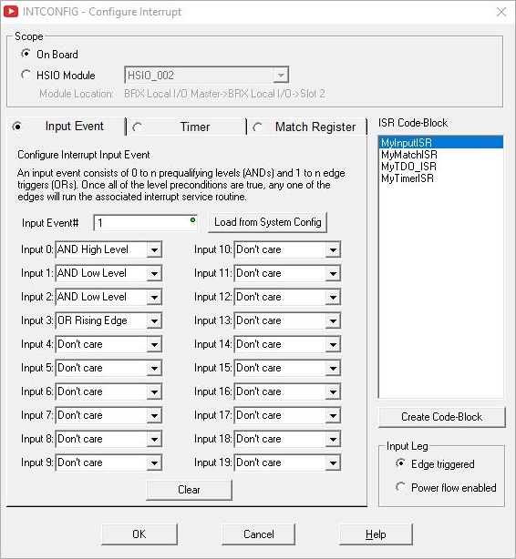
Input Event # selects which Input Trigger to create / modify. This can be a constant value of 1 to 4.
Load From System Config: if the selected Input Event # has already been defined in the System Configuration, clicking this button will load that configuration data into this dialog.
Input 0 - Input 19: when using the inputs on a BRX MPU, there are potentially 20 discrete inputs (0 - 19) that can be used in the trigger event depending on which MPU model is being used. Remember that only the first 10 on-board inputs are High-Speed inputs (denoted as HS on the dialog); any other inputs are standard speed (denoted as Std on the dialog). When using one of the BRX HSIO modules (BX-HSIO1, BX-HSIO2), there are 8 discrete inputs available for use in the trigger. All 8 of these inputs are High-Speed inputs.
The High-Speed discrete inputs allow for much quicker response times than the standard speed inputs. And while it's possible to select the standard speed inputs for use in the input event, the use of the High-Speed inputs will provide the responsiveness that is typically expected when using hardware interrupts. If the application requires both level inputs and edge inputs, it is possible that the standard speed inputs could work acceptably well as the level inputs, leaving the High-Speed inputs available for edge inputs which are required to be more responsive.
Don't Care (default) means this input is not part of the triggering event.
AND High Level: if this Input's level is HIGH (input is ON) this part of the trigger event is TRUE.
AND Low Level: if this Input's level is LOW (input is OFF) this part of the trigger event is TRUE.
OR Rising Edge: any time this Input's state changes from OFF to ON this part of the trigger event is TRUE.
OR Falling Edge: any time this Input's state changes from ON to OFF this part of the trigger event is TRUE.
OR Both Edges: any time this Input's state changes from OFF to ON then back to OFF this part of the trigger event is TRUE.
Clear All will set all of the available Input entries back to the default setting of Don't Care.
ISR Code-Block is the name of the Interrupt Service Routine to execute when the Input Event trigger happens.
Click Create Code-Block to create a new Interrupt Service Routine for this Input Event to execute. The ISR Code Block Configuration dialog will open where you can enter the name for the new ISR.
Input Leg selects which of the following power-flow conditions will cause this instruction to run:
- Edge Triggered
is the correct choice if this instruction is located in a Program, Task, Stage, or Subroutine.
- Because Interrupt Service Routines cannot detect edges, Power flow enabled is the only choice that will work if this instruction is located in an Interrupt Service Routine.
Timer Event
The BRX PLCs can use a hardware timer to create a Timer Event that will run an Interrupt Service Routine at either a precise, recurring interval or at a precise point in time. There can be up to 4 Timer Event triggers defined for the MPU itself and 4 for each BRX HSIO module.
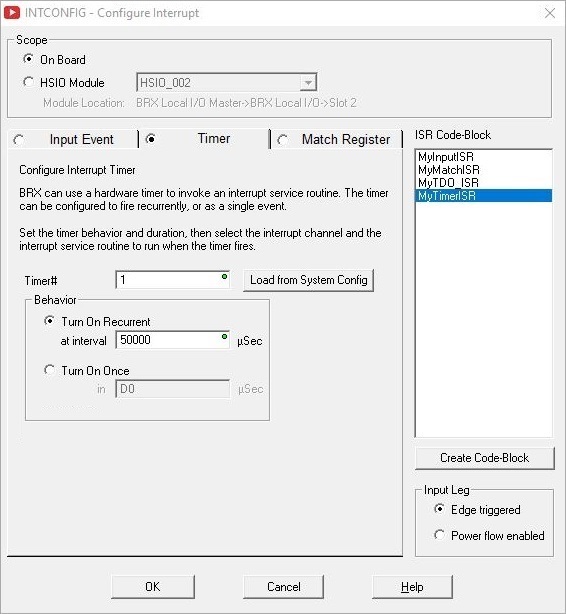
Timer # selects which Timer to create / modify. This can be a constant value of 1 to 4.
Load From System Config: if the selected Timer # has already been defined in the System Configuration, clicking this button will load that configuration data into this dialog.
Behavior specifies how the Timer will operate
Turn ON Recurrent means timer will run for the specified interval then the ISR Code-Block will be executed . This process will repeat at the specified interval as long as the CPU is in RUN mode. It is the user's responsibility make sure the time interval specified is long enough to allow the ISR Code-Block to run to completion before it is set to execute again. Use the INTDECONFIG - Deconfigure Interrupt instruction to stop this Timer from continuing to run.
Turn ON Once means the Timer will run for the specified interval then the ISR Code-Block will be executed one time.
ISR Code-Block is the name of the Interrupt Service Routine to execute once the Timer expires.
Click the Create Code-Block button to create a new Interrupt Service Routine for this Timer to execute. The ISR Code Block Configuration dialog will open.
Input Leg selects which of the following power-flow conditions will cause this instruction to run:
- Edge Triggered
is the correct choice if this instruction is located in a Program, Task, Stage, or Subroutine.
- Because Interrupt Service Routines cannot detect edges, Power flow enabled is the only choice that will work if this instruction is located in an Interrupt Service Routine.
Match Register
When one of the BRX CPU's on-board a High-Speed I/O inputs or one of the inputs on a BRX HSIO module (BX-HSIO1, BX-HSIO2) is configured for high speed counting, a register match operation can be used to generate a Match Register Event to run an Interrupt Service Routine. Once enabled, the ISR will be run each time the comparison operation transitions from "not a match" to "is a match". There can be up to 4 Match Register Event triggers defined for the MPU itself and 4 for each BRX HSIO module.
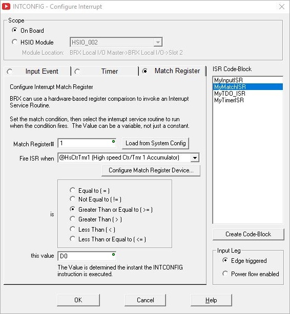
Match Register # selects which Match Register to create / modify. This can be a constant value of 1 to 4.
Load From System Config: if the selected Match Register # has already been defined in the System Configuration, clicking this button will load that configuration data into this dialog.
Fire ISR When specifies which of the High-Speed I/O input or output locations to use in the comparison. Choose from the following:
High-Speed Ctr / Tmr 1 Accumulator
High-Speed Ctr / Tmr 2 Accumulator
High-Speed Ctr / Tmr 3 Accumulator
Pulse Output 2 Position
Pulse Output 3 Position
Is specifies the math operator to use when preforming the comparison. Choose from the following:
Greater Than / Greater Than or Equal To
This Value specifies the 32-bit signed decimal value to compare to the register contents. This can be any value between -2147483648 and 2147483647 or any numeric location containing a value in that range. If this parameter is a numeric memory location, it's contents are read at the instant this INTCONFIG instruction is executed.
ISR Code-Block is the name of the Interrupt Service Routine to execute once the Match Register comparison is TRUE.
Click the Create Code-Block button to create a new Interrupt Service Routine for this Match Register to execute. The ISR Code Block Configuration dialog will open.
Input Leg selects which of the following power-flow conditions will cause this instruction to run:
- Edge Triggered
is the correct choice if this instruction is located in a Program, Task, Stage, or Subroutine.
- Because Interrupt Service Routines cannot detect edges, Power flow enabled is the only choice that will work if this instruction is located in an Interrupt Service Routine.
See Also:
INTCONFIG - Interrupt Configuration Editor
INTDECONFIG - Deconfigure Interrupt
INTSUSPEND - Suspend Interrupts
Related Topics:
Interrupt Service Routine Code Block Configuration
Interrupt Triggers in System Configuration