Topic: DMDlll0415

Dashboard
The Dashboard contains a graphical representation of the project's PLC system and panes of textual status information and links to utilities that are used to assist in configuration of the various components of the system, then monitoring and troubleshooting that system after it is up and running.
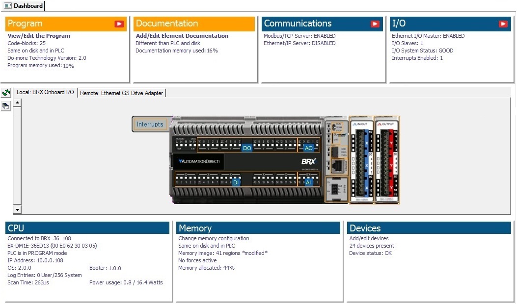
The upper and lower sections contain individual panes with entries that show the current status of things related to that pane. The entries in each pane are also links; clicking a link will either open a dialog that changes the configuration of that entry, or open a monitoring tool for that entry.
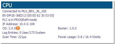
Entries that have an orange ! next to them indicate items that need your attention. For example, an orange ! adjacent to the "OS:" or "Booter:" items in the CPU section indicates the firmware in the CPU is older than the firmware you have downloaded to this PC. Click the link to open the firmware update tool.
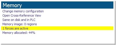
Some entries will have their text displayed with a yellow background to indicate the item is generating a warning message that may need your attention. For example, if you have Forces enabled and one or more items are currently being Forced to a value, the Memory section will display the " forces active" text with a yellow background. Click this link to open the Configure Forces dialog to see what elements are being forced.
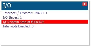
Some entries will have their text displayed with a red background to indicate the item is generating a warning message that may need your attention. For example, if an I/O module is reporting an error, the I/O section will display the "I/O System Status" text with a red background. Click this link to open the I/O System View to see an overview of the entire I/O system and locate the module that is reporting an error.
The title bar of some panes contains a "play video" icon. Clicking that icon will display a list of technical support videos that are appropriate for the entries in that pane. The last option in the video list will open the Browse Videos utility which will display a list of the videos that are related.
Floating / Docked
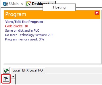
Right-clicking on the Dashboard tab will allow you to Float the Dashboard outside of Do-more Designer so that it can be placed in a screen location - like on a second monitor - that allows it be visible while other tabs in Do-more Designer are also accessible. Right-clicking on that tab while floating will allow you to uncheck the Floating attribute and return the Dashboard to its original location. Note: you can also click the Float / Dock button to the left of the scroll bar (circled in red in the image below) to float the Dashboard.
Reload the Dashboard
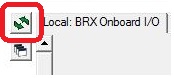
In the rare case that the on-screen representation of the PLC does not match the actual PC that is connected, or if the information in any of the panes appears out of date, clicking the Reload button will cause the Dashboard to regenerate the information in each pane which should synchronize the panes with the PLC.
There is one special case that you need to be aware of when you manually reload the Dashboard. The Do-more CPU keeps a copy of the last known good I/O Configuration data stored in it's battery-backed memory. While the system is powered down, if an I/O module is removed, or an I/O module is added, or an existing I/O module is moved to a different slot, or an existing I/O module is replaced with a different one, the collection of I/O modules will not match the collection that is in the battery-backed memory when the system is powered back on. The Do-more CPU will detect that the I/O modules in a PLC system changed during the power-cycle and will turn ON the System Information bit $InstIOChanged (ST134) - Module Configuration Changed at Power up.
If $InstIOChanged is ON when the Reload Dashboard is executed, the following dialog is displayed to assist in getting the online and offline I/O configurations m in synch:
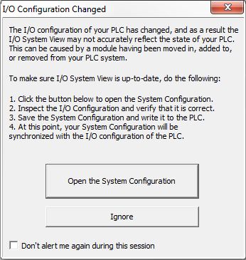
Open the System Configuration - click this button to open the System Configuration utility and display the I/O Configuration section which will read the current I/O configuration from the CPU then graphically show the detected I/O modules. At this point a decision needs to be made as to which copy of the I/O Configuration is correct.
If the currently detected I/O modules are correct - click the OK button to overwrite the offline copy of the I/O configuration with the I/O configuration data read from the CPU. Notice at this point that the 'Write to PLC' button is enabled which allows the updated version of the project to be downloaded to the CPU which will synchronize the PLCs contents with the offline project.
If the currently detected I/O modules are NOT correct - click the CANCEL button to leave the offline copy of the configuration intact, which will leave the offline copy out of sync with the online copy. At this point you should take whatever corrective action is required to get the I/O modules in the online configuration to match the configuration stored in the offline project.
Ignore - button to close the dialog and leave the project's copy of the configuration intact, which will leave the offline copy out of sync with the CPU's copy. At this point you should take whatever corrective action is required to get the I/O modules in the online configuration to match the configuration stored in the offline project.
Don't alert me again during this session - click this option to keep this alert dialog from being displayed any more while the current session of Do-more Designer is open.
Note: if the $BatteryLow (ST149) and the $InstIOChanged (ST134) are ON at the same time the Do-more CPU will power up in PROGRAM mode because the copy of the last known good copy of the I/O Configuration will NOT be present when the aforementioned comparison is done. This is a potentially serious condition that needs to be resolved before allowing the system to be put back into service. Refer to the Help section on Changing the CPU Battery to resolve the Battery Power Low indication.
Warning!: If you absolutely need for the CPU to go into RUN mode with the CPU in this low battery power condition then you will need to visually determine if the currently detected I/O Configuration is valid for the use by the project in the CPU then use either the Mode Switch on the front of the CPU or Do-more Designer's PLC Mode utility to manually place the CPU in RUN mode.
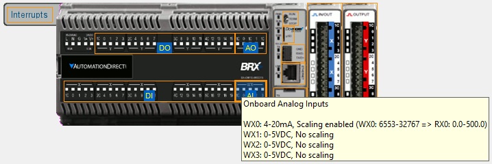
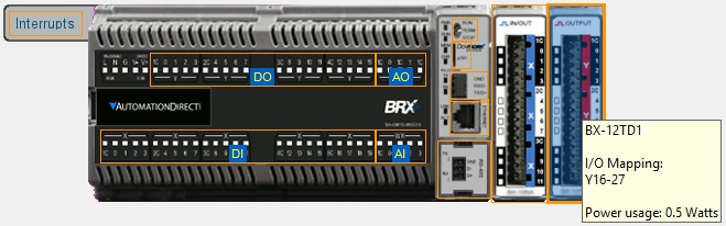
The center section contains a series of tabbed graphical representations of the PLC systems components. The leftmost (top) selection is the local base with the CPU. There is an additional tab for each Ethernet Remote I/O Slave. Any time the mouse cursor is in the center section orange outlines - known as hotspots - will appear on the sections of the PLC system to indicate there is status information available for that area or configuration that can be done to that area.
Hovering the mouse cursor over any of the hot spots will display a tooltip that shows the current status of the item in that hotspot.
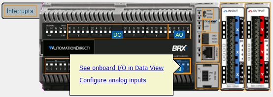
Left-clicking on the hot spot will display a popup tip that contains links specific to the configuration tools and information displays for that item.
Right-clicking on the CPU section will display the context menu that contains a list of operations that can be performed on the CPU; right-click on a module will display a list of operations that can be performed on that module.
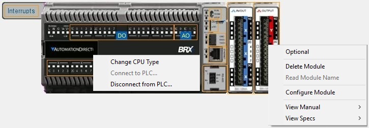
Depending on the PLC family that list will contain one or more of the following:
See I/O in Data View - open a new Data View that contains all of the I/O points on the selected I/O Module with Status enabled.
Edit I/O Mapping - open the I/O Mapping page of the System Configuration so you can change the module 's current map location.
Optional (DL205 Systems only) - marks the I/O module as optional, this is discussed in detail below.
Delete Module - remove this I/O module from the base (only applicable if the I/O Master's Configuration Mode is set to "manual").
Read Module Name - reads the part number of an I/O module based on the module ID read from that slot.
Configure Module - opens the appropriate configuration dialog (only enabled for I/O modules that must be configured prior to use).
View Manual - opens a submenu where the actual part number of the I/O module can be selected, this will then open the default web browser, which will then open a page on Automationdirect's web site that contains links to the User Manual. This requires a functioning connection to the Internet.
View Specs - opens a submenu where the actual part number of the I/O module can be selected, this will then open the default web browser, which will then open a PDF file on Automationdirect's web site that displays the specification pages from the catalog. The Spec pages contain hardware requirements and wiring diagrams. This requires a functioning connection to the Internet and a PDF viewer.
See Also:
Do-more Designer Programming Windows