Topic: DMD0062

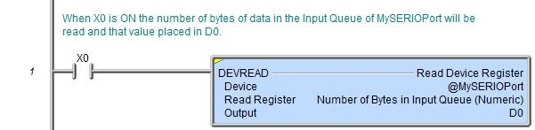
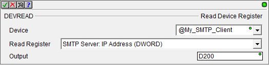
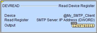
DEVREAD - Read Device Register
When the PLC system powers up, the Module Configurations and Device Configurations are read from the PLC's ROM and a copy is placed into the PLC's RAM. The Read Device Register (DEVREAD) instruction is used to read the current value in the registers - this does not read the register values stored in the System Configuration in ROM, it only changes the values in the PLC's RAM copy.
The individual registers that can be read, and what those values mean are defined by the Device that is being accessed. The companion instruction DEVWRITE - Write Device Register can used to write new values to the RAM copy of the Device registers.
Parameters:
Note: Use the F9 key or click the 'three dot box' at the right edge of the parameter field to open the Default Element Selection Tool (the Element Picker or the Element Browser) or use the Down-Arrow key (Auto-Complete) on any parameter field to see a complete list of the memory locations that are valid for that parameter of the instruction.
Device selects which of the configured Devices, or which Device Reference to read from.
No devices
availablemeans there is no device that is appropriate for
this instruction. Select one of the following to create the required device:
create device will open the Device Configuration dialog of the System Configuration to create a new device of the appropriate type.
create module will open the Module Configuration dialog of the System Configuration to create a new module configuration that can provide a device of the appropriate type.
Read Register selects which register in the selected Device or Device Reference to read. The valid entries for the Read Register are determined by the Device selected . See the table below for the valid registers for each Device.
Output is a numeric memory location to store the value that has been read from the Device. This can be any writable numeric location of the appropriate size.
|
Read Register
|
Output |
Notes:
|
|
If the selected Device is an SMTP Client the following options are valid:
|
||
|
SMTP Server: SMTP IP Address (DWord)
|
Returns a DWord containing the IP Address of the SMTP Server the SMTP Client is configured to use.
|
Use the 'IP Address' format selection in a Data View to see the IP Address stored in the DWord location in it's traditional dot-decimal notation (000.000.000.000).
|
|
SMTP Server: SMTP IP Port (Word)
|
Returns a Word containing the TCP/IP Port Number the SMTP Client is configured to use
|
|
|
SMTP Server: POP3 IP Address (DWord)
|
Returns a DWord containing the IP Address of the POP3 Server the SMTP Client is configured to use.
0 = the POP3 process is using the same IP Address as the SMTP Server.
Non-0 = the POP3 process is using an IP Address separate from the SMTP Server.
|
Use the 'IP Address' format selection in a Data View to see the IP Address stored in the DWord location in it's traditional dot-decimal notation (000.000.000.000).
|
|
SMTP Server: POP3 IP Port (Word)
|
Returns a Word containing the POP3 Port Number the SMTP Client is configured to use.
|
|
|
Returns a String containing the Name of the SMTP Server the SMTP Client is configured to use.
|
||
|
SMTP Server: "From" EMail Address (String)
|
Returns a String containing the data in the Authentication "From Email Address "field of the SMTP server configuration.
|
|
|
SMTP Server: Authentication Account Password (String)
|
Returns a String containing the data in the Authentication "Password "field of the SMTP server configuration.
|
|
|
SMTP Server: Authentication Account User Name (String)
|
Returns a String containing the data in the Authentication "User Name "field of the SMTP server configuration.
|
|
|
SMTP Server: Authentication Mode (Word)
|
Returns a Word containing the Authentication Mode the SMTP Client is configured to use.
0 = Disabled 1 = AUTH Login
|
|
|
|
Returns a Word containing the Timeout value (in seconds) the SMTP Client is configured to use.
|
|
|
If the selected Device is an MQTT Client the following options are valid:
|
||
|
MQTT Client: Authentication: Account Password (String)
|
Returns a String containing the currently configured Password for the selected MQTT Client device.
|
|
|
MQTT Client: Authentication: Account User Name (String)
|
Returns a String containing the currently configured User Name for the selected MQTT Client device.
|
|
|
MQTT Client: Client ID (String)
|
Returns a String containing the currently configured Client ID for the selected MQTT Client device.
|
|
|
MQTT Client: LW&T Payload (String)
|
Returns a String containing the currently configured Topic for the Last Will & Testament for the selected MQTT Client device.
|
|
|
MQTT Client: LW&T Topic (String)
|
Returns a String containing the currently configured Payload for the Last Will & Testament for the selected MQTT Client device.
|
|
|
MQTT Client: Server IP Address (DWord)
|
Returns a DWord containing the IP Address of the MQTT Broker the MQTT Client is configured to connect to.
|
|
|
MQTT Client: Server Name (String)
|
Returns a String containing the Name of the MQTT Broker the MQTT Client is configured to connect to.
|
|
|
MQTT Client: Server Port (DWord)
|
Returns a Word containing the Port Number the MQTT Client is configured to use.
|
|
|
MQTT Client: Comm Timeout (in seconds) (DWord)
|
Returns a DWord containing the Comm Timeout the MQTT Client is configured to use when establishing the connection to the MQTT Broker.
|
|
|
MQTT Client: User Specified Client ID ( String)
|
Returns a String containing the current Client ID.
|
|
|
If the selected Device is an FTP Client the following options are valid: |
||
|
FTP Client: Authentication: Account Password (String)
|
|
A String containing the data for the Authentication "Password "field of the FTP Client configuration.
|
|
FTP Client: Authentication: Account User Name (String)
|
|
A String containing the data for the Authentication "User Name "field of the FTP Client configuration.
|
|
FTP Client: Server IP Address (DWord)
|
|
Use the 'IP Address' format selection in a Data
View to see the IP Address stored in the DWord location in it's traditional
dot-decimal notation (000.000.000.000). The Name to IP Address (DNSLOOKUP) instruction can be used to find the IP Address assigned to a named device at runtime.
|
|
FTP Client: Server Name (String)
|
|
A String containing the data for the "Server Name "field of the FTP Client configuration.
|
|
FTP Client: Server Port (DWord)
|
0 - 65535
|
The Port Number the FTP Client will use to establish the connection to the FTP Server.
|
|
FTP Client: Timeout (in seconds) (DWord)
|
0 - 255 |
The amount of time (in seconds) the FTP Client will wait for a response from the FTP Server when it tries to establish the connection to the FTP Server. |
|
If the selected Device is a UDP Connection the following option is valid:
|
||
|
|
Returns a single bit value indicating whether a packet is present in the input queue.
ON = at least one packet is available. OFF = no packets are available.
|
|
|
If the selected Device is a TCP Client Connection the following options are valid:
|
||
|
Number of Bytes in Input Queue (Numeric)
|
Returns a DWord containing the number of bytes of data currently in the Ethernet port's input buffer.
|
|
|
Number of Bytes in Output Queue (Numeric)
|
Returns a DWord containing the number of bytes of data currently in the Ethernet port's output buffer.
|
|
|
If the Device is a TCP Server Connection the following options are valid:
|
||
|
Number of Bytes in Input Queue (Numeric)
|
Returns a DWord containing the number of bytes of data currently in the Ethernet port's input buffer.
|
|
|
Number of Bytes in Output Queue (Numeric)
|
Returns a DWord containing the number of bytes of data currently in the Ethernet port's output buffer.
|
|
|
If the Device is a POM (Pluggable Option Module) the following options are valid:
|
||
|
POM Mode (Numeric) |
Returns a Word containing the protocol the POM is currently configured to use:
0: Do-more Protocol (for Programming, HMIs, etc.)
4: Program Control (STREAMIN / STREAMOUT for ASCII and Custom Protocols)
255: No POM Installed
|
|
|
|
Returns a Word containing the type of POM currently installed:
0: Unknown POM type
1: USB: BX-P-USB-B or BX-P-USB-C
2: Ethernet: BX-P-ECOMLT (Ethernet with RJ-45 connector, server only)
3: Serial: BX-P-SER2-TERM (RS-232 with 3-pin header)
4: Serial: BX-P-SER4-TERM (RS-485 with 3-pin header)
5: Serial: BX-P-SER2-RJ12 (RS-232 with RJ-12 connector)
6: Serial: BX-P-SER422-TERM (RS-422 with 5-pin header)
7: Serial: BX-P-SER2-TERMFC (RS-232 with 5-pin header for RTS / CTS flow control)
8: Ethernet: Advanced Protocol POM - (see DST80 for specific POM ID)
9: Ethernet: BX-P-ECOMEX (RJ-45 connector, Secondary Port for BX-DM1E)
255: N0 POM Installed
|
|
|
If the selected Device is the on-board Serial Port or any of the Serial ports on a SERIO module the following options are valid:
|
||
|
Number of Bytes in Input Queue (Numeric)
|
Returns a DWord containing the number of bytes of data currently in the serial port's input buffer.
|
|
|
Number of Bytes in Output Queue (Numeric)
|
Returns a DWord containing the number of bytes of data currently in the serial port's output buffer.
|
|
|
Serial Port: Status (Numeric, 32, Bit of Word)
|
Returns a DWord that contains the following bits: 0x01 = the CTS line of the serial port is
asserted 0x32 = reserved
|
|
|
|
Returns a DWord containing the currently configured baud rate. It will be one of the following values:
115200 57600 38400 19200 9600 4800 2400 1200
|
|
|
Serial Port: Data Bits (7, 8)
|
Returns a Word containing the currently configured data size. It will be one of the following values:
7 = 7 data bits 8 = 8 data bits
|
|
|
|
Returns a Word containing the currently configured number of stop bits. It will be one of the following values:
1 = 1 Stop Bit 2 = 2 Stop Bits
|
|
|
Serial Port: Parity (0: None, 1: Even, 2: Odd)
|
Returns a Word containing the currently configured parity setting. It will be one of the following values:
0 = No Parity 1 = Even Parity 2 = Odd Parity
|
|
|
Serial Port: Transmit / RTS Control
|
Returns a Byte containing the currently configured number of Transmit Control setting an RTS control setting.
0x0? = Unconditional 0x2? = Delayed for 5ms 0x3? = Delayed for 50ms 0x4? = Delayed for 250ms 0x5? = Delayed for 500ms
0x?1 = Manual
|
A BYTE value where High Nibble is the Transmit Control value and the Low Nibble is the RTS Control value.
If any of the 'Delayed for XXXms' selections are specified the RTS Control value will automatically be
set to 0x00 - Follows Transmitter. Note: To reference a bit value in a numeric element use a bit cast operation.
For example: use D10:0 to reference bit 0 of DWord D10 use D8:31 to reference bit 31 of DWord D8 |
|
Serial Port: Manual RTS Control Line Value (0 or 1)
|
Returns a Byte containing the currently configured level of the RTS line.
0x00 - the RTS line of the serial port is Low
|
The low nibble of the Transmit / RTS Control value must be set to 1 (Manual) to enable programmatic control of the RTS line.
|
|
If the selected Serial Port or Serial Port POM is Configured as a K-Sequence Slave (Server) the following option is valid:
|
||
|
Serial Port: K-Sequence Slave Station ID
|
Returns a Word containing the currently configured number Station ID. It will be a value in the following range:
1 - 90
|
|
|
If the selected Serial Port or Serial Port POM is Configured as a Modbus/RTU Slave (Server) the following option is valid:
|
||
|
Serial Port: Modbus/RTU Slave Unit ID
|
Returns a Word containing the currently configured number Unit ID. It will be a value in the following range:
0 to 255
|
|
|
If the selected Serial Port or Serial Port POM is Configured as a Modbus/RTU Master (Client) the following options are valid:
|
||
|
Serial Port: Modbus/RTU Master Inter-packet Delay (uSec)
|
Returns a Word containing the currently configured inter-packet delay. It will be a value in the following range:
0 to 65535
|
The amount of time (in microseconds) the Modbus/RTU Client will place between all packets as they are sent.
|
|
Serial Port: Modbus/RTU Master Timeout (ms)
|
Returns a Word containing the currently configured Timeout value. It will be a value in the following range:
0 to 32767
|
|
|
Serial Port: Modbus /RTU Master Retries
|
Returns a Word containing the currently configured number of retries. It will be a value in the following range:
0 to 255
|
|
Status Display:
The yellow triangle in the upper left corner of the status display indicates this is a Multi-scan instruction.
See Also:
DEVREAD - Read Device Register
DEVWRITE - Write Device Register
Related Topics:
HWINFO - Get Hardware Information
For more information on Devices, Device References, and how to configure them go to the Device Configuration Section under System Configuration.
Rung Example: