Topic: DMD0344

DNSLOOKUP - Name to IP Address
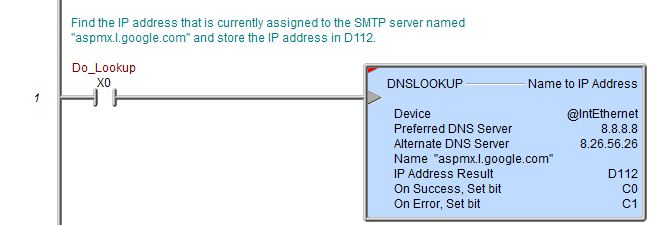
The Name to IP Address (DNSLOOKUP) instruction is used to find the IP Address assigned to the named device using the Domain Name System protocol (DNS). This instruction uses the on-board Ethernet port and requires that the TCP/IP network be setup so the CPU has a functional connection to a DNS Server.
The Name needs to consist only of the server name, not a fully qualified URL. For example, the Name field should contain only the text "mail.google.com", not "https://mail.google.com". The timeout value (including retries) for the DNS Lookup operation is fixed in the DNS client at 126 seconds.
If the DNS Lookup operation is successful, the IP address will be stored in a DWord location. Use the "IP Address" format in a Data View to see the returned IP Address in the traditional dot-decimal notation (000.000.000.000).
Parameters:
Note: Use the F9 key or click the 'three dot box' at the right edge of the parameter field to open the Default Element Selection Tool (the Element Picker or the Element Browser) or use the Down-Arrow key (Auto-Complete) on any parameter field to see a complete list of the memory locations that are valid for that parameter of the instruction.
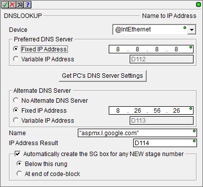
Device - selects which of the Ethernet Devices to use, currently this instruction can only use @IntEthernet which is the on-board Ethernet port on the Do-more CPU. If the only entry in the list is no devices available this indicates that there are no Devices that can execute this instruction, most likely cause is the CPU does not have an on-board Ethernet port.
Preferred DNS Server - the TCP/IP Address of the first DNS server to contact for resolving the Name to an IP Address. The default value is 8.8.8.8 (decimal 34744072) which is Google's public DNS Server.
- Fixed Address
- the IP Address assigned to the DNS Server. IP addresses
are canonically represented in dot-decimal notation, consisting of four
decimal numbers, each ranging from 0 to 255, separated by dots.
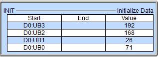
- Variable IP Address - the IP Address resides in a memory location in the CPU. This allows the IP Address to be changed at runtime. This can be any readable DWord numeric location. Each octet of the IP Address is stored in one byte of the Variable Address location. In the example below the Initialize Data instruction will use the :UB operator to place the 4 octet values of IP Address 192.168.26.71 into the 4 Bytes of the DWord location D0 in the proper order.
The 'IP Address' format selection in a Data View can be used to see the IP Address stored in the DWord location in the traditional dot-decimal notation (000.000.000.000).
Click the Get PC's DNS Server Settings button to retrieve the Preferred DNS Server and the Alternate DNS Server IP Addresses from the network configuration of the PC running Do-more Designer and use those IP Addresses in this instruction.
Alternate
DNS Server - the TCP/IP Address of an alternate DNS server to contact
if the preferred DNS server cannot resolve the Name to an IP Address.
The default value is the Secondary DNS Server IP address from the network
setup on the computer that is running Do-more Designer.
-
No Alternate DNS Server - select this option to only use the Preferred DNS Server to resolve the Name
- Fixed Address
- the IP Address assigned to the Alternate DNS Server. IP addresses
are canonically represented in dot-decimal notation, consisting of four
decimal numbers, each ranging from 0 to 255, separated by dots.
- Variable IP Address - the IP Address resides in a memory location in the CPU. This allows the IP Address to be changed at runtime. This can be any readable DWord numeric location. Each octet of the IP Address is stored in one byte of the Variable Address location. In the example below the Initialize Data instruction will use the :UB operator to place the 4 octet values of IP Address 192.168.26.71 into the 4 Bytes of the DWord location D0 in the proper order.
The 'IP Address' format selection in a Data View can be used to see the IP Address stored in the DWord location in the traditional dot-decimal notation (000.000.000.000).
Name - specifies the name to resolve to an IP Address. This can be a string literal (text within double quotes), or any system-defined Short Strings, or system-defined Long Strings, or user-defined Strings. The Name is not a fully qualified URL like "https://mail.google.com"; use only the "mail.google.com" portion of the URL.
IP Address Result - designates a location to store the IP Address if a DNS server can successfully resolve the Name. This can be any writable numeric location.
The On Success and On Error parameters specify what action to perform when this instruction completes. You do not have to use the same type of selection for both On Success and On Error.
If the Set Bit selection is used for either On Success or On Error, the specified BIT location will be SET OFF when the instruction is first enabled and will remain OFF until the instruction completes. Once complete, the appropriate Success or Error bit location ON. The specified Bit location is enabled with a SET (Latch) operation meaning that it will remain ON even if the input logic for the instruction goes OFF.
If the JMP to Stage selection is used for either On Success or On Error the target Stage must be in the same Program code-block as this instruction, you cannot specify a target Stage that exists in a different Program code-block. When the operation finishes, the target Stage will be enabled the same way as a standalone Jump to Stage (JMP) instruction would do it. The JMP to Stage option will only be available if this instruction is placed in a Program code-block.
On Success selects which of the following actions to perform if the operation is successful:
- Enable SET Bit then specify any writable bit location.
- Enable JMP to Stage then specify any
Stage number from S0 to S127 in the current Program code-block.
On Error selects which of
the following actions to perform if the operation is unsuccessful:
- Enable SET Bit then specify writable bit location.
- Enable JMP to Stage then specify any Stage number from S0 to S127 in the current Program code-block.
If either the On Success or On Error selections are set to JMP to Stage, Automatically create the SG box for any NEW stage number will be enabled which will automatically create any target stage that does not already exist.
- Below this rung will create the new target stage on a new rung following this instruction.
- At end of code-block will create the new target stage as the last rung of this Program.
Status Display:
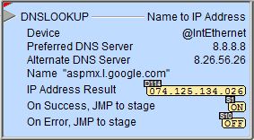
The red triangle in the upper left corner of the status display indicates this is a Fully Asynchronous instruction.
The gray triangle at the right end of the input leg indicates the input is edge-triggered, meaning this instruction will execute each time the input logic transitions from OFF to ON.
See Also:
DNSLOOKUP - Name to IP Address
Related Topics
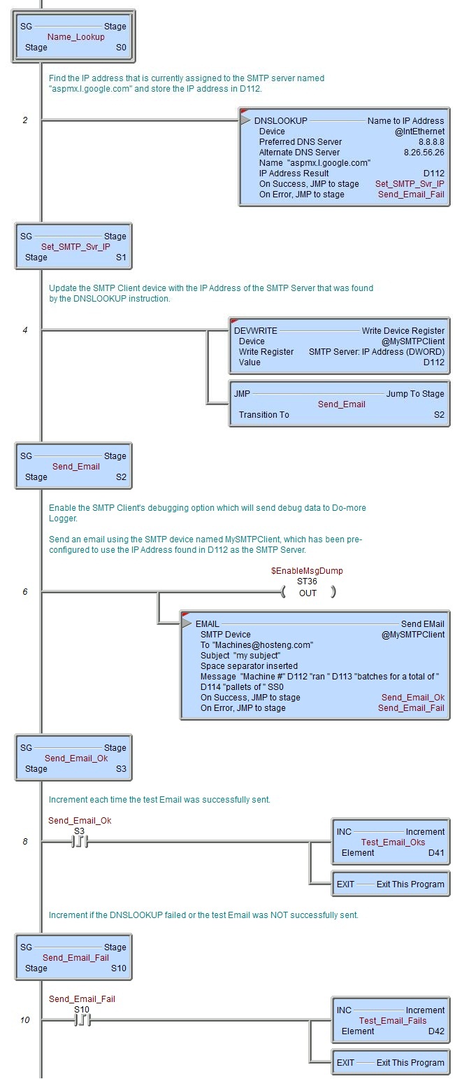
Example Using Stages:
Rung Example: