Topic: DMD0255

System Information
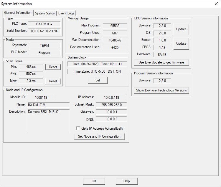
The System Information utility provides tabbed views of the runtime status of the Do-more CPU, messages generated by the CPU, and system events that are logged by the CPU. The System Information utility is invoked by selecting the PLC-> System Information menu selection, or clicking the Info button on the Online toolbar.
General Information
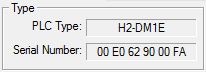
The Type group
displays the type of CPU hardware and identification:
PLC Type displays the type of CPU hardware:
BX-DM1-x is a BRX Series Do-more CPU
BX-DM1e-x is a BRX Series Do-more CPU with on-board Ethernet
H2-DM1 is a DL205 Series Do-more CPU
H2-DM1E is a DL205 Series Do-more CPU with on-board Ethernet
T1H-DM1 is a Terminator I/O Series Do-more CPU
T1H-DM1E is a Terminator I/O Series Do-more CPU with on-board Ethernet
Serial Number is the 12 digit serial number of the CPU
Do-more CPUs without on-board Ethernet is a serialized number assigned at the factory
Do-more CPUs with on-board Ethernet is the MAC address of the Ethernet port
DM-SIM this is the MAC address of the primary Ethernet adapter in the PC running the Do-more Simulator
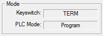
The Mode group displays the current PLC mode information:
Keyswitch is the current position of the front panel keyswitch
RUN means the keyswitch is in the RUN position
PLC Mode displays the current PLC mode
Run means the CPU is in executing the ladder logic program in the CPU
Program means the CPU is not in executing the ladder logic program in the CPU
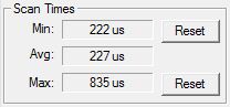
The Scan Times group displays the CPU's current scan time information since the last PGM-to-RUN mode change or press of the Reset button :
Min is the shortest scan time
Avg is the average of all the scan times
Min is the longest scan time
Note: click the associated Reset button to clear the Min and / or Max scan time.
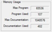
The Memory Usage group displays how much of the CPU's program storage is being utilized:
Max Program is the maximum amount of
storage in the CPU for ladder logic.
Program Used is the amount of program
storage utilized by the currently loaded project.
Max Documentation is the maximum amount
of storage in the CPU for rung comments and element documentation.
Documentation Used is the amount of documentation storage utilized by the currently loaded project.
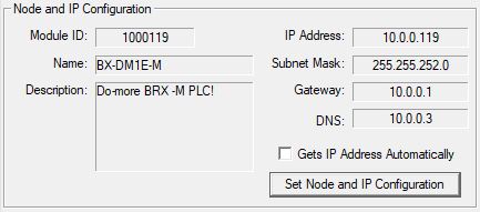
The Node and IP Configuration group displays the current Node configuration and the setup of the on-board Ethernet port (on models that have them). These values are initially configured by the NetEdit utility. Once the IP Address information has been set. the values of the fields are also stored in the CPU's memory in these locations: $IPAddress (DST18), $NetMask (DST19), $Gateway (DST20).
Gets IP Address Automatically will be checked if the on-board Ethernet port obtained its IP Address, Subnet Mask and Gateway Address from a DHCP server. Note: the on-board Ethernet port (@IntEthernet) did not support DHCP until Do-more Technology Version 2.8.
Click the Set Node and IP Configuration button to open a dialog that will allow the programmer to change these entries. Note: this is a convenient way to change the TCP/IP configuration of a CPU through the USB or Serial port which allows the programmer change to the TCP/IP configuration of a CPU that is not properly configured to be part of the local network.
The Module ID can be any positive constant number.
The Name can be any 255 character combination of alphanumeric and punctuation characters. The Module ID and Names entered must be unique on the network where the CPU will be connected.
The Description can be any 255 character combination of alphanumeric and punctuation characters.
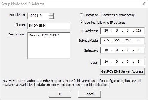
The IP Address information can be setup in one of two ways:
- Enable the Obtain an IP Address automatically (use DHCP) option to have the on-board Ethernet port obtains its IP Address, Subnet Mask and Gateway Address from a DHCP server. Note: the on-board Ethernet port (@IntEthernet) did not support DHCP until Do-more Technology Version 2.8.
The TCP/IP Address information can be entered as a static address in the following four fields.
IP Address can be any valid TCP/IP Address. The IP Address entered must be unique on the network where the CPU will be connected.
Subnet Mask can be any valid TCP/IP Subnet Mask.
Gateway can be any valid TCP/IP address of a network Gateway.
DNS can be any valid TCP/IP address of a DNS server on the network. Click the Get PC's DNS Server Address to read that information from the PC running Do-more Designer.
Once the IP Address information has been set by either of the above methods, that information will be reflected in the system-memory locations $IPAddress (DST18), $NetMask (DST19), $Gateway (DST20). For Do-more CPUs that do not have an on-board Ethernet port, these fields are not used for configuration purposes, but these fields can still be used for identification by manually storing identifying values there.
Setting the Date, Time, and Time Zone
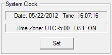
The System Clock group displays the current date, time, and time zone in the CPU. A full discussion of how the Date and Time are handled can be found in the help topic Date and Time Overview.
Do-more CPUs store the date and time internally in UTC (Coordinated Universal Time), and generates the local time ($Now) by applying a time zone adjustment (which is specified in minutes).
The Time Zone can be adjusted at runtime by changing the system variable $TimeZone (DST384). Be aware that the time zone is specified in minutes relative to UTC. For example, US Eastern Time is UTC -300 minutes, so $TimeZone would contain the value of -300.
Do-more CPUs can further adjust for Daylight Saving Time, but this adjustment is done manually to avoid conflict with widely varying local laws. Daylight Saving Time can be adjusted at runtime through the system variable $SummerTime (ST768). Setting $SummerTime to 'true' automatically adds one hour to the local time.
Click the Set button to open the Set PLC Clock dialog with the following options:
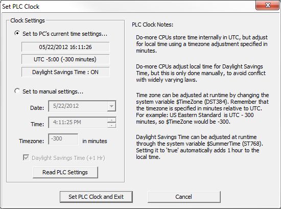
The Clock Settings group selects how the System Clock will be set:
Set to PC's current time settings ... displays the current date, time, and time zone settings from the PC running the Do-more Designer programming software.
Set to manual settings ... allows you to manually enter the date, time and time zone settings:
Date: clicking the down arrow will display a calendar from which you can select the date.
Time: clicking the up and down arrows will change the time.
Time zone: enter the number of minutes relative to UTC.
Click the Daylight Savings Time checkbox to automatically add one hour to the local time.
Click the Read PLC Settings button to read the current date, time, and time zone settings from the CPU.
Click the Set PLC Clock and Exit button to update the date, time, and time zone settings, then close the dialog
Click the Cancel button to close the dialog and leave the date, time, and time zone settings intact.
Updating the CPU Firmware
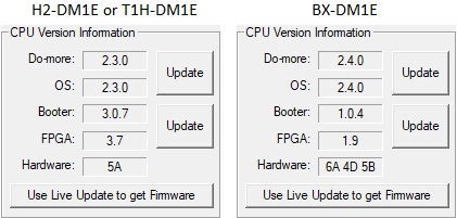
The CPU Version Information group displays the current version of the hardware and software in the Do-more CPU, and provides a facility to download the latest firmware and update the CPU.
Do-more is the Do-more Technology version of the operating system in the CPU.
OS is the current version of the operation system in the CPU.
Click the Update button adjacent to the Do-more &/ OS display to open the Update Operating System dialog.
Booter is the current version of boot loader in the CPU.
FPGA is the current version of the Gate Array code in the CPU.
Click the Update button adjacent to the Booter & FPGA display to open the Update Gate Array and Loader dialog.
Hardware shows the revision of the PWBs of the CPU. The H2 Series and Terminator Series PLCs only have a single PWB, so they show a single hardware revision number. The BRX PLCs have three PWBs (the CPU board, an input I/O board and an output I/O board), they the will show a revision number for each PWB.
Note: Live Update requires a functional Internet connection to work, make sure the Internet connection is active before running Live Update.
Click the Use Live Update to get Firmware button to open the Live Update dialog. Live Update will utilize the internet connection to check for new firmware files for the Do-more CPU and the CTRIO modules, then download any new files to the appropriate Bin\Images\< Device > folders.
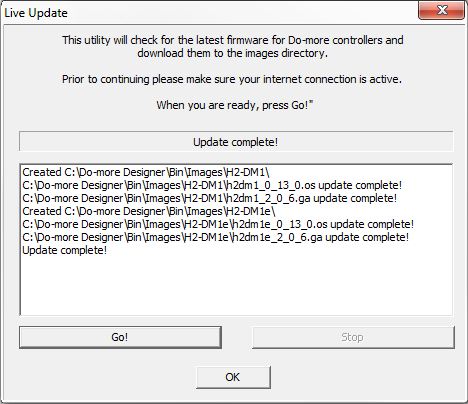
Click the Go! button to check for updated firmware files.
Click the OK button to close the LiveUpdate dialog.
Note: DIP switch #3 is used to Enable/Disable the ability to update the firmware in the CPU. This DIP switch must be OFF to allow Do-more Designer to update the operating system or the gate array. Follow this link for more information on the CPU's DIP switches.
If running the Live Update process downloaded new Operating System firmware, click the Update button to open the Update Operating System dialog. When the dialog opens it will read the OS Version and Do-more versions from the currently connected CPU, and from the latest operating system firmware file.
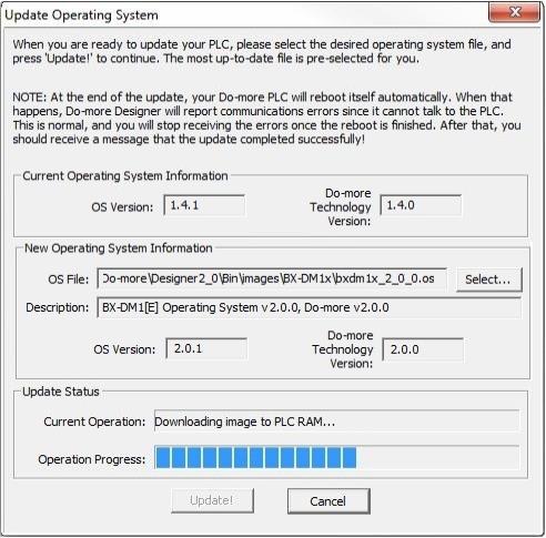
Current Operating System Information
OS Version is the current version of the operation system in the CPU
Do-more Version is the current version of the instruction set in the CPU
New Operating System Information
OS File is the most up-to-date operating system firmware file in the default firmware folder
Click Select... to open a dialog to select an operating system firmware file. Operating System firmware files typically have the following form: "H2DM1x_<major>_<minor>_<build>.os"
Description is the current version information from the selected file
OS Version is the current version of the operation system in the selected file
Do-more Version is the current version of the instruction set in the selected file
Click the Update! button to begin the update progress. The last phase of updating the operating system is a reboot of the Do-more CPU. While the CPU is rebooting, the normal communication updates will fail, and the Link indicator on the Status bar will turn red. Once the CPU has successfully rebooted, normal communication updates will automatically resume, and the Link indicator will return to normal.
Click the Cancel button to exit without updating the operating system.
Note: There is no fail-safe for the Gate Array and Loader update, which means, if the update process begins and then fails , ** DO NOT TURN OFF THE POWER**, keep trying the update process until it is successful. If you turn off the power without a successful update the CPU must be sent back to the factory for repair (use the 'H/W Repair (RMA)' link at www.hosteng.com to request an RMA number for a Do-more CPU that fails to update the Gate Array and Loader).
If running the Live Update process downloaded new Gate Array firmware, click the Update button to open the Update Gate Array and Loader dialog. When the dialog opens it will read the Gate Array Version and Boot Loader versions from the currently connected CPU, and from the latest Gate Array firmware file.

Current Gate Array and Loader Information
Booter Version is the current version of Boot Loader in the CPU
Gate Array Version is the current version of the Gate Array code in the CPU
New Gate Array and Loader Information
GA File is the most up-to-date Gate Array firmware file in the default firmware folder
Click the Select... button to open dialog to select a Gate Array firmware file. Gate Array files firmware file typically have the following form: "BXDM1x_<major>_<minor>_<build>.ga"
Description, Booter Version, and Gate Array Version show the current version information from the selected file.
Click the Update! button to begin the update progress.
Click the Cancel button to exit without updating the Gate Array and Loader.
Program Version Information
Displays the version of the currently running Do-more Designer programming software.
Click the Show Do-more Technology Versionbutton to open the Do-more Technology Version utility to show detailed information for all of the components that make up the Do-more system.
See Also:
General information