Topic: DMD0301

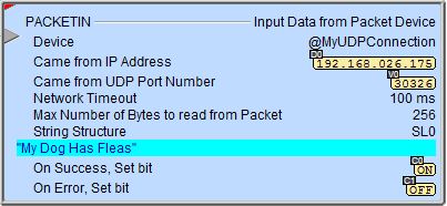
PACKETIN - Input Data from Packet Device
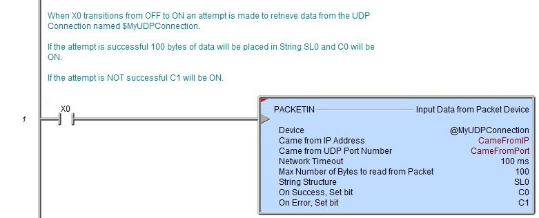
The Input Data from Packet Device (PACKETIN) instruction is used to retrieve data from the CPU's on-board Ethernet using a predefined UDP Connection and store that data in either a String (if the data is ASCII text; maximum of 1024 bytes) or a numeric data block (if the data is binary; maximum of 1536 bytes). The UDP connection device has an input buffer that can hold up to 16 packets of 1536 bytes each. Any packets received while the UDP Connection's input buffer is full will be lost.
It is important to know that each time this instruction is executed it will retrieve an entire packet from the UDP Connection and copy the number of bytes specified in the instruction into specified storage location then the entire packet is purged from the UDP Connection's input buffer. Any characters that were read from that packet but not stored locally will be discarded.
Each UDP Connection's associated structure contains a Bit named .PacketAvailable which will be ON any time that the Packet Device's input buffer has a packet ready to be retrieved. This Bit can be used as a trigger for the PACKETIN instruction. The Clear Device (DEVCLEAR) instruction can be used to delete all of the exiting packets in the UDP Connection's input buffer and reset the .PacketAvailable flag.
Parameters:
Note: Use the F9 key or click the 'three dot box' at the right edge of the parameter field to open the Default Element Selection Tool (the Element Picker or the Element Browser) or use the Down-Arrow key (Auto-Complete) on any parameter field to see a complete list of the memory locations that are valid for that parameter of the instruction.
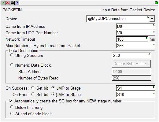
Device specifies which UDP Connection devices to retrieve the data from.
Device selects one of the existing UDP Connections.
create device indicates that there are no UDP Connections that have been configured to perform this instruction. Selecting this option will invoke the New Device configuration page of the System Configuration dialog where a UDP Connection device can be created.
Came from IP Address is a memory location to store the IP address of the Ethernet device that sent the UDP packet. This is the value to use for the TCP/IP Address in a PACKETOUT instruction if you need to generate a response packet. Since this value is always a 4-byte hexadecimal value, the memory location to store the value must be a DWord location. This can be any readable DWord location.
Note: the IP Address in the packet is not in the traditional 'dotted decimal' IP Address format of www.xxx.yyy.zzz, there are four hexadecimal bytes 'packed' into a DWord. Use the IP Address display format in Data View to show the this value in the dotted decimal format.
Came from UDP Port Number is a memory location to store the UDP Port Number specified in the received UDP packet. This is the value to use for the UDP Port number in a PACKETOUT instruction if you need to generate a response packet. This value is always a decimal value in the range of 0 - 65535. This can be any readable Word location.
Network Timeout is the maximum amount of time (in milliseconds) to allow the instruction to wait before signaling a completion. This value is a constant in the range of 1 to 65535. In the event that the Network Timeout causes the completion of the instruction, any input data that has been received up to that point will be discarded.
Max Number of Bytes to read from Packet is the number of bytes to copy from the Packet Device to the Data Destination location. This can be any readable numeric location or any constant value from 1 to 1536. If the value specified is smaller than the number of bytes actually in the buffer, only the specified number of bytes will be copied to the Data Destination location, any remaining bytes will be discarded.
Data Destination is where the data that has been read from the Packet Device will be stored. The option chosen will depend on the type of data that is received from the Packet Device. If the data is ASCII text the most appropriate choice is String Structure. If the data is binary (simple bytes of data) the appropriate choice is a user-created numeric block of bytes.
If the data is ASCII String Structure is a String
to store the data.
This can be any of the system-defined Short Strings (SS, up to 64 bytes), or system-defined Long Strings (SL, up to 256 bytes), or a user-defined String, which can be a maximum of 1,024 bytes.
If the data is binary Numeric Data Block is a memory block to store the data.
If an Unsigned Byte data block does not already exist, or if you want to create an additional Unsigned Byte data block, then click the Create Byte Buffer... button to open the following dialog where you can create a new data block of Unsigned Bytes.
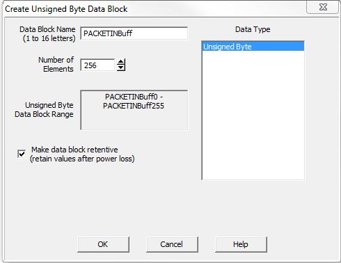
The Data Block Name (1 to 16 letters) must be unique, and consist of 1 to 16 characters (A-Z, a-z; no numbers, no spaces). The default name PACKETInBuff can be changed if desired.
Number of Elements is the number of bytes in the data block. The data blocks must be created on a DWord (4-byte) boundary. The maximum number of Bytes that can be received from a single packet is 1536.
Unsigned Byte Block Range displays the first and last element of the block that will be created based on the current entries for Data Block Name and Number of Elements.
Data Type means the data block will consist of Unsigned Bytes.
Make Data Block Retentive (retain values after power loss) means a data block marked as retentive will hold its state through a power cycle or a Program-to-Run mode transition. The status of memory NOT marked as retentive will be cleared at power up and during a Program-to-Run mode transition.
Start Address is the offset
in the numeric data block to begin storing the data read from the UDP
Connection.
Number of Bytes Read is a numeric memory location to store the number of bytes that were read from the UDP Connection and stored in the designated location. The maximum number of bytes that can be received in a single packet is 1536.
The On Success and On Error parameters specify what action to perform when this instruction completes. You do not have to use the same type of selection for both On Success and On Error.
If the Set Bit selection is used for either On Success or On Error, the specified BIT location will be SET OFF when the instruction is first enabled and will remain OFF until the instruction completes. Once complete, the appropriate Success or Error bit location ON. The specified Bit location is enabled with a SET (Latch) operation meaning that it will remain ON even if the input logic for the instruction goes OFF.
If the JMP to Stage selection is used for either On Success or On Error the target Stage must be in the same Program code-block as this instruction, you cannot specify a target Stage that exists in a different Program code-block. When the operation finishes, the target Stage will be enabled the same way as a standalone Jump to Stage (JMP) instruction would do it. The JMP to Stage option will only be available if this instruction is placed in a Program code-block.
On Success selects which of the following actions to perform if the operation is successful:
- Enable SET Bit then specify any writable bit location.
- Enable JMP to Stage then specify any
Stage number from S0 to S127 in the current Program code-block.
On Error selects which of
the following actions to perform if the operation is unsuccessful:
- Enable SET Bit then specify writable bit location.
- Enable JMP to Stage then specify any Stage number from S0 to S127 in the current Program code-block.
If either the On Success or On Error selections are set to JMP to Stage, Automatically create the SG box for any NEW stage number will be enabled which will automatically create any target stage that does not already exist.
- Below this rung will create the new target stage on a new rung following this instruction.
- At end of code-block will create the new target stage as the last rung of this Program.
Packet Device Structure Fields:
An Input Packet from Packet Device instruction will reference a Packet Device![]() A pre-configured device that is capable of communicating via UDP/IP protocol through the on-board Ethernet port of a Do-more CPU. .
A pre-configured device that is capable of communicating via UDP/IP protocol through the on-board Ethernet port of a Do-more CPU. .
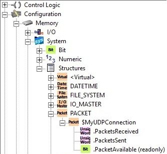
Each Packet device has an associated structure which contains the following member fields:
.PacketsReceived (Read / write) is a 16-bit Unsigned value that shows the number of packets that have been successfully retrieved from the UDP Connection's input buffer.
.PacketsSent (Read / write) is a 16-bit Unsigned value that shows the total number of packets that have been successfully sent from the UDP Connection's output buffer.
.PacketAvailable (Read-only) is a Bit that will be ON any time there is at least one packet in the UDP Connection's input buffer.
Status Display:
The red triangle in the upper left corner of the status display indicates this is a Fully Asynchronous instruction.
The gray triangle at the right end of the input leg indicates the input is edge-triggered, meaning this instruction will execute each time the input logic transitions from OFF to ON.
The Status display for the String or Numeric Block will only display as many of the characters of the destination location as will fit within the borders of the instruction, typically this is about 50 characters.
See Also:
PACKETIN - Input Data from Packet Device
PACKETOUT - Output Data to Packet Device
UDP Connection Device Configuration
Related Topics:
STREAMIN - Stream In Data from Device
STREAMOUT - Stream Out Data to Device
Example Using Stages:
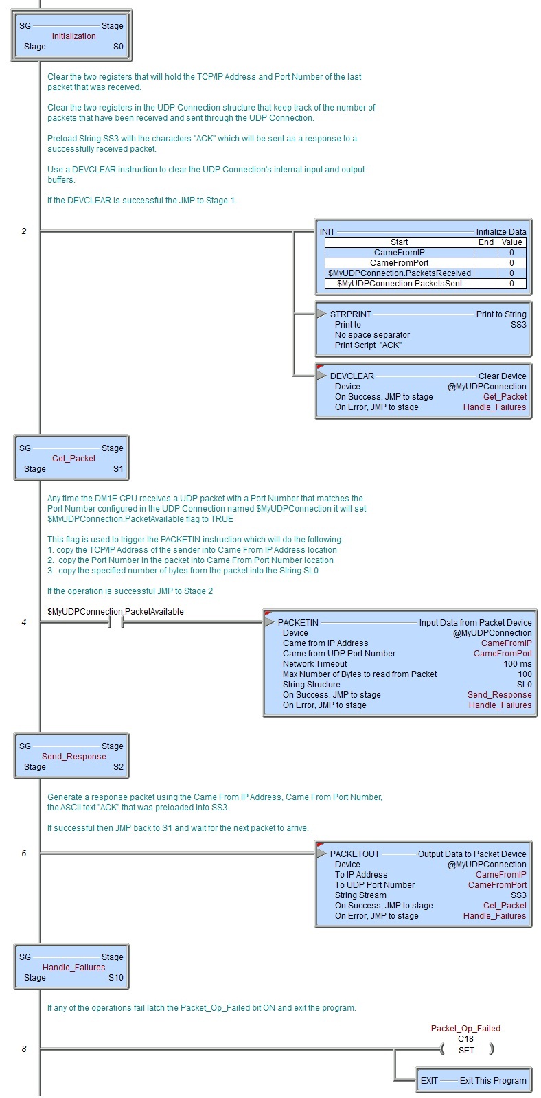
Rung Example: