Topic: DMD0420

Data Blocks
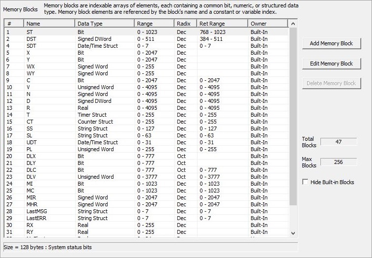
Selecting the Memory Blocks tab will display a list of the currently defined memory blocks. This tab has functions that allow you to Add additional memory blocks, Edit existing memory blocks, and Delete unused memory blocks (built-in memory blocks can not be deleted, only user-created memory blocks can be deleted).
Total Blocks shows the number of currently defined memory blocks and Max Blocks shows the maximum number of memory blocks allowed base on the memory capacity of the selected CPU. Checking Hide Built-in Blocks will remove the Built-in memory blocks from the list, leaving only the user-defined memory blocks in the list.
Adding Additional Memory Blocks
Clicking the Add Memory Block button will open the following dialog where you can create new memory block:
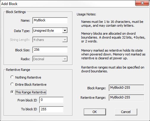
Block Settings define the characteristics of the memory block as follows:
Name is the name of the block.
Data Type selects the type of data that each element in the block will contain:
- Bit : each element in the block is a single Bit (0 or 1).
- Unsigned Byte : each element in the block is an Unsigned Bytes that can hold a value of 0 to 255.
- Signed Byte : each element in the block is a Signed Bytes that can hold a value of -128 to 127.
- Unsigned Word : each element in the block is an Unsigned Word that can hold a value of 0 to 65535.
- Signed Word : each element in the block is a Signed Word that can hold a value of -32768 to 32767.
- Signed DWord : each element in the block is a Signed Word that can hold a value of -2,147,483,648 to 2,147,483,647.
- Real : each element in the block is a Real (floating point) location that can hold a value of -3.4e+038 to 3.4e+038.
- Timer Struct : each element in the block is a Timer structure.
- Counter Struct : each element in the block is a Counter structure.
- String Struct : each element in the block is a String structure. String Length - (only valid if the Data Type is String) specifies the maximum length of each String in the
block.
- PID Struct : each element in the block is a PID structure.
- Date / Time Struct : each element in the block is a Date / Time structure.
- Task Struct : each element in the block is a Task structure.
- Rampsoak Struct : each element in the block is a Ramp / Soak profile structure.
- Program Struct : each element in the block is a Program structure.
- DeviceRef Struct : each element in the block is a DeviceRef structure.
- Drum Struct : each element in the block is a Drum structure.
- FileHandle : the heap item will be a FileHandle structure
Block Size is the desired number of elements in the Block. Memory blocks are allocated on DWord (32-bit, 4-byte, or 2-Word) boundaries.
Radix is the desired radix (Decimal or Octal) of the memory block IDs.
Retentive Range Settings - Memory marked as retentive will hold its state through a power cycle or a Program-to-Run mode transition. The status of memory NOT marked as retentive will be cleared at power up and during a Program-to-Run mode transition. This setting only applies to the data value in the CPU's memory, it does not store of copy the retentive data value in the offline copy of the project. If you ALSO want to store of copy of the data value with the offline project you will need to use the Memory Image Manager to add this memory block to the memory image file that is part of the offline project. Select one of the following three options:
- Nothing Retentive : none of the memory locations in the memory block will be retentive.
- Entire Block Retentive : all of the memory locations in the memory block will be retentive.
- This Range Retentive : only this range of the memory locations in the memory block will be retentive. The range is defined by From Block ID (the ID of the first element in the range) and To Block ID (the ID of the last element in the range).
See Also:
Memory View edit and / or monitor the contents of the Memory Blocks and Strings.
Memory Image Manager is used save a copy of the contents of the retentive memory locations and heap items in the offline Do-more Designer project.
Related Topics: