Topic: DMD0422

User Data Types
Selecting the User Data Types tab will display a list of the currently defined user data types, and any memory blocks or heap items that have been created with those types definitions. This tab has functions that allow you to Add additional user data types, Edit existing user data types, and Delete unused user data types (you can only delete a user data type that has NOT been used to create heap items or memory blocks).
The Show group has three radio buttons select which classes of structure definitions to show in the list. Selecting User Data Types will only show the user-created data types, selecting Built-in Structs will only show the structure definitions that were automatically built for the project, and selecting Both will display both the user-created and built-in structure definitions.
The contents of user data types can be sourced from an external CSV file. Clicking the Import button and selecting a CSV file will import the contents of that CSV file into the current list of user data types. Import and Export is the preferred way to move user data types between Do-more designer projects. Refer to the section below on the format of data in the import file. Clicking the Export button and selecting a CSV file will write the contents of the selected built-in structures or user data types to that CSV file. Exporting the contents of built-in structures is for documentation purposes only, they cannot be imported back into a project.
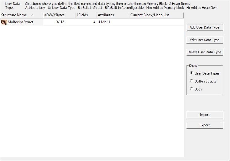
The center section is a list of the currently defined user data types. The list can be sorted by any of the columns by clicking on the column's header. For each user data type listed the following data is shown:
Structure Name is the name of the user data type definition.
#DW / #Bytes shows the size of the structure that will be created with this definition in both the number of DWords and the number of Bytes.
#Fields shows the total number of fields in the structure definition.
Attributes describes how the structure definition was created:
U (User) means this is a user-created structure definition.
Bi (Built-in) means this is for a predefined structure.
BiR (Built-in Reconfigurable) means this structure definition was automatically created for use by a device, and will be changed in response to changes made to the device, meaning that structure fields can be added or deleted from the structure as the user changes the configuration of the device.
D (Deep) means this structure contains a nested structure.
Mb (Blocks) means this structure definition can be used to make memory blocks of these structures, it will appear in the Data Type list in the Add Memory Block dialog.
N (Nestable) means this structure can be nested a UDT. Structures can be nested one level deep; you can embed a structure within a UDT as long as that structure does not contain a structure itself.
H (Heap Item) means this structure definition can be used to make heap items of these structures, it will appear in the Data Type list in the New Heap Item dialog.
Current Block / Heap List shows the names of both memory blocks and heap items that have been created with this structure definition.
Adding a New User Data Type
Structure Name contains the name of the structure definition User data type names must follow Nickname Rules![]() Nicknames can be 1 to 16 characters in length and consist of any combination of alphanumeric characters and underscores ('_', 'a-z', 'A-Z', 0-9), no spaces or punctuation marks are allowed, and must begin with a letter or an underscore.. Because you are creating a structure definition - not an actual structure - it is recommended that you append the letters "Struct" to whatever name you want to use. This follows the pattern of System and Built-in structure definitions already in Do-more Designer. Doing this will greatly help in keeping the user data type definitions and the actual structures made with those user data types straight.
Nicknames can be 1 to 16 characters in length and consist of any combination of alphanumeric characters and underscores ('_', 'a-z', 'A-Z', 0-9), no spaces or punctuation marks are allowed, and must begin with a letter or an underscore.. Because you are creating a structure definition - not an actual structure - it is recommended that you append the letters "Struct" to whatever name you want to use. This follows the pattern of System and Built-in structure definitions already in Do-more Designer. Doing this will greatly help in keeping the user data type definitions and the actual structures made with those user data types straight.
Number of DWords shows the size of the user data type in DWords. Each user data type can be a maximum of 64 DWords in length.
Any time after a field has been added, you can click the View Memory Layout button to see a graphical depiction of how the memory will be packed into the structure.
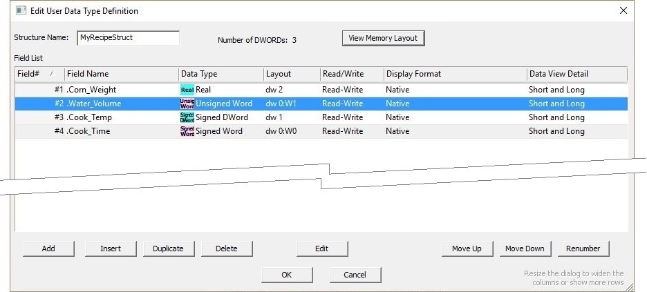
Add will add a new field at the end of the list and open the Field Definition dialog, and Insert will add a new field immediately before the highlighted field and open the Field Definition dialog.
Duplicate will add a copy of the highlighted field at the end of the list with a new name that is typically the original name with a number appended.
Edit opens the highlighted field in the Field Definition dialog so that its definition can be changed.
Delete removes the highlighted field from the user data type.
Each click of the Move Up / Move Down moves the highlighted field one position closer to the beginning or to the end of the list respectively.
The list of Field's can be sorted by any of the columns by clicking on the column header. If you have sorted the list by any column other than Field#, clicking the Renumber button will reassign the Field#'s based on the current sort order. Doing this will cause the layout of the memory in the user data type to be shifted to match the renumbered fields.
Field Name contains the name of the field in this user data type. All field names must follow Nickname Rules![]() Nicknames can be 1 to 16 characters in length and consist of any combination of alphanumeric characters and underscores ('_', 'a-z', 'A-Z', 0-9), no spaces or punctuation marks are allowed, and must begin with a letter or an underscore. and field names must be unique with each user data type.
Nicknames can be 1 to 16 characters in length and consist of any combination of alphanumeric characters and underscores ('_', 'a-z', 'A-Z', 0-9), no spaces or punctuation marks are allowed, and must begin with a letter or an underscore. and field names must be unique with each user data type.
Field Number contains a sequential number that uniquely identifies each in the structure. Some Built-in structures may have field numbers that are skipped. This number is automatically assigned when the field is created, and is automatically adjusted as need if the field is moved within the user data type. The can be a maximum of 255 fields in each user data type.
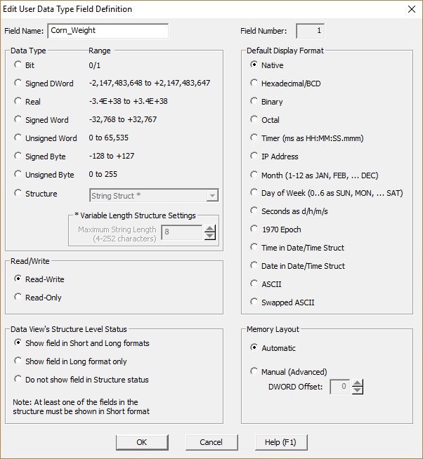
Data Type selects the type of data this field will contain. This can be any of the native simple, or any of the system-defined structures and existing UDTs that are marked as Nestable.
Structures can be nested one level deep, meaning you can embed a structure within a UDT as long as that structure does not contain a structure itself. The drop-down list will contain the list of system-defined structures and any existing UDTs that can be nested in this UDT.
Variable Length Structure Settings are used if the selected structure's length is variable. If so, you must specify the maximum length of that structure. The structure field will be created with this maximum length.
If the selected structure is a String, Maximum String Length (4 - 252 characters) specifies the largest number of characters this String field can contain. UDT memory is allocated in DWord (4-byte) chunks, so this value must be on DWord boundaries.
Layout shows the memory layout of the individual fields in the structure. Each field is contained within a DWord. Depending on the data of the field, it will consume either the entire DWord, or a Word, a Byte or a Bit within that DWord.
Read-Write / Read-Only specifies whether the contents of the field can be changed by the ladder logic program or by an external communication source. The Copy Memory (MEMCOPY) instruction is the only way to get values into fields marked as Read-Only.
Data View's Structure Level Status selects when this field will be displayed in Data View. This selection lets you govern the level of detail that will appear when the structure is displayed in a Data View. Critical members can be tagged for Short. Useful members can be tagged for Short and Long. One-shot bits or non-critical members could be tagged as Do Not Show.
- Show Field in Short and Long Formats this field will be displayed any time a structure made with this user data type is shown in a Data View.
- Show Field in Long Format Only this field will only be displayed when a structure made with user data type is shown in a Data View and either "long multi line" or "long single line" display format is selected.
- Do Not Show Field in Structure Status this field will not be displayed as part of the structure element’s status in a Data View. You can still see these fields individually in a Data View, like MyData.MyField element, but not part of MyData element. You cannot select this option for every field, there must be at least one field in every user data type that is displayed.
Default Display Format selects the initial format of the data when it is displayed in a Data View. This is very useful if the field contains a numeric value that should be interpreted a certain way. For example, if the value is the Preset of a Timer which is a number of milliseconds, a better default format for this field is to display it in Timer format (hh:mm:ss.mmm).
Memory Layout selects how the memory layout process will happen:
- Automatic means this dialog will pack the fields as densely as possible to minimize the amount of data consumed by the structures created with this user data type.
- Manual (Advanced) means the user will manually choose the location of the field within the structure. Depending on the Data Type selected for this field, you will have control of the DWord Offset which specifies the DWord in the structure where this field will be located, and Word Offset which specifies the Word offset within that DWord (0 or 1), or the Byte Offset which specifies the Byte offset within that DWord (0 - 3), or Bit Offset which specifies the Bit offset within that DWord (0 - 31).
Import File Format
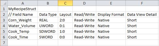
The contents of user data types can be sourced from an external CSV file. Clicking the Import button and selecting a CSV file will import the contents of that CSV file into the current list of user data types. The import process will skip any user data types that already exist in the project. The format of a CSV file is show in the following spreadsheet (rows that begin with a "//" are just documentation):
Structure Name contains the name of the structure definition User data type names must follow Nickname Rules![]() Nicknames can be 1 to 16 characters in length and consist of any combination of alphanumeric characters and underscores ('_', 'a-z', 'A-Z', 0-9), no spaces or punctuation marks are allowed, and must begin with a letter or an underscore.. Because you are creating a structure definition - not an actual structure - it is recommended that you append the letters "Struct" to whatever name you want to use. This follows the pattern of System and Built-in structure definitions already in Do-more Designer. Doing this will greatly help in keeping the user data type definitions and the actual structures made with those user data types straight.
Nicknames can be 1 to 16 characters in length and consist of any combination of alphanumeric characters and underscores ('_', 'a-z', 'A-Z', 0-9), no spaces or punctuation marks are allowed, and must begin with a letter or an underscore.. Because you are creating a structure definition - not an actual structure - it is recommended that you append the letters "Struct" to whatever name you want to use. This follows the pattern of System and Built-in structure definitions already in Do-more Designer. Doing this will greatly help in keeping the user data type definitions and the actual structures made with those user data types straight.
Data Type specifies the type of data this field will contain, specified by one of the following keywords:
BIT (bit) which can have a value of 0 or 1.
SBYTE (signed byte) which can have a value of -128 to 127.
UBYTE (unsigned byte) which can have a value of 0 to 255.
SWORD (signed word) which can have a value from -32768 to 32767.
UWORD (unsigned word) which can have a value of 0 to 65535.
SDWORD (signed double word ) which can have a value of -2,147,483,648 to 2,147,483,647.
REAL (floating point) which can have a value of -3.4e+38 to 3.4e+38.
Layout specifies memory layout of the individual fields in the structure. Each field is contained within a DWord. Depending on the data type of the field, it will consume either the entire DWord, or a Word, a Byte or a Bit within that DWord. The layout is specified as 2 digits separated by a colon. The first digit is the DWord offset in memory of the DWord where the data will reside, the second digit is the offset of that data within that DWord.
A DWord will consume all the DWord field so this digit will be 0.
A Word will consume either the high word or low word location in the DWord so this digit will be either 1 (high) or 0 (low).
A Byte will consume one of the four possible byte locations in the DWord so this digit will be either 3 (high), 2 (next), 1 (next), or 0 (low).
A Bit will consume of the possible 32 bit locations in the DWord so this digit will be 32 (high), 31 (next) ... 0 (low).
Read-Write / Read-Only specifies whether the contents of the field can be changed by the ladder logic program or by an external communication source. The Copy Memory (MEMCOPY) instruction is the only way to get values into fields marked as Read-Only. The valid keywords are Read-Only and Read-Write.
Display Format specifies the initial format of the data when it is displayed in a Data View. This is very useful if the field contains a numeric value that should be interpreted a certain way. For example, if the value is the accumulator of a Timer, the proper interpretation is the number of milliseconds. Any time this field is displayed in a Data View or a relational contact, the specified default display format will be used instead of the native value. These are the valid keywords:
Native
Timer (in milliseconds)
Month (1 - 12 corresponds to JAN - DEC)
Day-of-Week (0 - 6 corresponds to SUN - SAT)
Seconds-DHMS ( Days / Hours / Min / Sec )
Time-DateTime (same format as Time in a Date / Time Structure)
Date-Date-Time (same format as Date in a Date / Time Structure)
ASCII-Swapped
Data View Detail specifies whether this field will be displayed in the short form or the long form when this structure is shown in a Data View. Valid keywords for this field are: Short which means the field will be displayed on both the short and long forms, Long which means the field will only be displayed in the long form, and No which means the field will not be displayed on either form.
See Also:
Memory View edit and / or monitor the contents of the Memory Blocks and Strings
Memory Image Manager is used save a copy of the contents of the retentive memory locations and heap items in the offline Do-more Designer project.
Related Topics: