Topic: DMD0494

Modbus I/O Scanner Monitor
After the Modbus I/O Scanner is configured and running, the Modbus Scanner Monitor can be used to display the "health" of the currently configured network of Modbus Scanner Devices. This utility can be opened through by selecting the Debug -> Modbus Scanner Monitor menu selection.
The Scanner Monitor can show the status of 8 of the possible 32 Scanner devices at a time. When the Scanner Monitor is first opened, the first 8 configured Scanner Devices (1 thru 8) will automatically be selected. If there are more than 8 Scanner Devices configured, the remaining Scanners will be automatically selected on one the next three pages. The 4 buttons in the lower left corner of the dialog will select the current page of Scanner Devices (1 - 8), (9 - 16), (17-24), and (25 - 32).
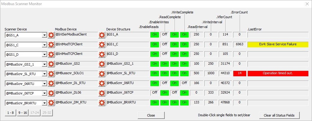
The Scanner Device selects from the list of configured Scanner Devices. The buttons below the Scanner Device column (1-8, 9-16, 17-24, 25-31) switch between the 4 pages of 8 scanner devices.
The Modbus Device displays the name of the Modbus Client Device the Modbus Scanner is using to perform the Modbus Reads and Writes.
The Device Structure displays the name of the Modbus Scanner's associated structure whose fields are used for status and runtime control of the Modbus Scanner Device. The structures fields and their current values are listed below:
.EnableReads and .EnableWrites show the current state (ON / OFF) of those two Bits. Double-clicking on either field will toggle that Bit to the opposite state.
.ReadComplete and .WriteComplete show the current state (ON / OFF) of those two Bits. Double-clicking on either field will toggle that Bit to the opposite state.
.ReadInterval and .WriteInterval show the current values of those two numeric fields. Double-clicking on either field will open an editor where a new value can be entered.
.XferCount and .ErrorCount show the current values for those numeric fields. Double-clicking on either field will reset the field's value to 0.
.Last Error is the last error received from the Modbus Read and Write operations performed by the Scanner Device. Double-clicking on that field will clear the error text.
When the Scanner Device sends a Modbus Read or Write to a Modbus server one of four possible events can occur from the request:
If the server receives the Read or Write request without a communication error, and the server can process the Read or Write operation normally, it returns a normal response.
If the server receives the Read or Write request, but detects a communication error (parity, LRC, or CRC), no response is returned. The Scanner Device will eventually process a timeout condition for the query. Note: the timeout value is defined in the Modbus TCP Client or the Modbus/RTU Client.
If the server receives the Read or Wrote request without a communication error, but cannot process the request because it is invalid ( for example the request is to Read or Write a non-existent coil or register), the server will return an exception response. List of Modbus Exception Response Codes.
If the server does not receive the Read or Write request due to a communication error, no response is returned. The Scanner Device will eventually process a timeout condition for the query. Note: the timeout value is defined in the Modbus TCP Client or the Modbus/RTU Client.
Clicking the Clear All Status Fields button will reset the .XferCount and .ErrorCount fields to 0, and clear the .LastError field for all of the Scanner Devices on the current page (it does NOT clear these values for Scanner Devices on other pages).
See Also:
Modbus I/O Scanner Configuration
Modbus I/O Scanner Monitor
Related Topics:
MSREGRD - Modbus I/O Scanner Register Read
MSREGWR - Modbus I/O Scanner Register Write