Topic: DMD0514

JMP - Jump To Stage
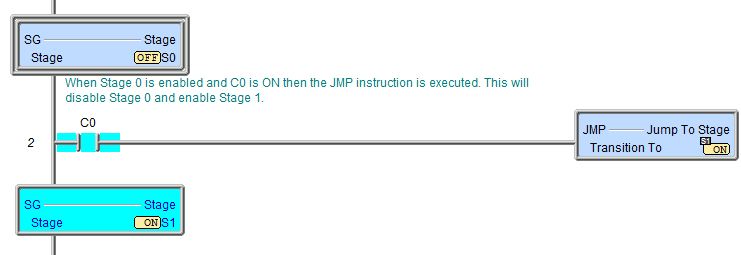
The Jump To Stage (JMP) instruction is used to transition from one stage to another stage by disabling the stage which contains the Jump to Stage instruction, and enabling the target stage that is specified in the instruction.
It is important to note that when this instruction is executed, it does NOT cause an immediate move to the target stage; it simply enables the target stage. The effect of this instruction will occur the next time the target stage is normally processed as part of the CPU's scan. This means if the target stage is "below" this stage in the Program, the target stage will execute on the same scan as the JMP instruction; if the target stage is "above" this stage in the Program, the target stage will execute on the scan following the JMP instruction.
The effect of this instruction will occur the next time the affected stages are normally processed as part of the CPU's scan. When a stage becomes disabled, on the next scan the disabled stage executes Termination Logic where Output (OUT) coils are turned OFF and Timers are reset.
Like all of the other stage programming instructions this one must be placed in a Program; stage instructions cannot be placed in a Task, a Subroutine, or an Interrupt Service Routine. Stage programming instructions can only reference stages in the same Program code block, they cannot reference stages in a different Program code block.
To switch between displaying the fully qualified stage reference ($Main.S0) and the abbreviated name (S0), go to the View -> Options -> Ladder Tab -> Misc. Options and check the 'Abbreviate Stage Names (Use S0 over $Main.S0)' option.
For a complete discussion on Stage Programming and how to use the Stage programming instructions effectively, refer to the Help Topic on Stage Programming Concepts.
Parameters:
Note: Use the F9 key or click the 'three dot box' at the right edge of the parameter field to open the Default Element Selection Tool (the Element Picker or the Element Browser) or use the Down-Arrow key (Auto-Complete) on any parameter field to see a complete list of the memory locations that are valid for that parameter of the instruction.
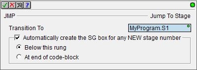
Transition To is the target stage of the transition. The target stage can only be a stage in the same Program; it cannot reference a stage in a different Program. The stage reference can be entered using its fully qualified name (for example MyProgram.S0 through MyProgram.S127) or simply its stage number (for example S0 through S127).
Automatically create the SG box for any NEW stage number: if the target Stage number does not exist it can be automatically created.
- Below this rung means the target stage will be created on a new run following this instruction.
- At end of code-block means the target stage will be created as the last rung of the Program.
Status Display:
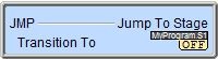
The status display shows whether or not that stage is enabled (ON) of disabled (OFF).
See Also:
JMP - Jump To Stage
SGRSTI - Indexed Disable Stage
SGRSTR - Disable Range of Stages
SGDIVRG - Jump to Multiple Stages
SGCONVRG - Converge Multiple Stages to SG
Related Topics:
Stage Programming Concepts
Example 1 - A Simple 2-State Process
Example 2 - A Lamp On / Off Controller
Example 3 - A Garage Door Opener
Review - Steps to Writing Successful Stage Programs
Example 1 of 2:
Description of a Jump To Stage Diagram:
This is a stage diagram of a simple sequence control that would fill a vessel, stir its contents and then drain. It is good to imagine the sequence before actually writing the ladder logic.
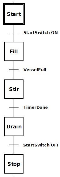
Initially stage 'Start'
Stage 'Fill' fills the vessel. Once the vessel is full (VesselFull = ON), the process transitions to stage 'Stir'.
Stage 'Stir' stirs for a period of time. Once the time to stir is complete (TimerDone = ON), the process transitions to stage 'Drain'.
Stage 'Drain' empties the contents of the vessel. Once it is decided the vessel is drained, the StartSwitch is flipped OFF and the job is done.
Ladder Logic for the above Stage Diagram:
This is a ladder logic equivalent to the above stage diagram.
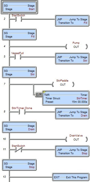
Once the Program code block containing this stage is first enabled to run, the initial stage 'Start' will be enabled because it is the initial stage (designated by the double border). None of the ladder logic in other stages ('Fill', 'Stir', 'Drain', 'Stop') is executed; only Rung 2. Once StartSwitch comes ON the JMP (Jump To Stage) instruction is executed. This instruction disables stage 'Start', and enables stage 'Fill' so that only the ladder logic in stage 'Fill' is being executed (i.e. Rungs 4-5).
Once stage 'Fill' is enabled Pump turns ON to power the pump motor so that product will begin to fill the vessel. Once the level detector input, VesselFull comes ON, the JMP instruction is executed. This instruction disables stage 'Fill' and enables stage 'Stir'. Also, since stage 'Fill' is now disabled, all of the OUT coils in that stage will be turned OFF (i.e. Pump will go OFF).
Once stage 'Stir' is enabled StirPaddle turns ON to power the stir-paddle motor so that the product can be stirred. Also TMR (StirTimer) begins to time. After 15 minutes of stir time, TimerDone bit comes ON which will execute the JMP instruction. This instruction disables stage 'Stir' and enables stage 'Drain'. Also, since stage 'Stir' is now disabled, all the OUT coils in that stage will be turned OFF and all the timers will be reset.
Once stage 'Drain' is enabled DrainValve turns ON to open the valve for the product to drain out of the vessel. Once StartSwitch turns OFF the JMP instruction is executed. This instruction disables stage 'Drain' and enables stage 'Stop'. Since stage 'Drain' is now disabled, all OUT coils in that stage will be turned OFF.
Once stage 'Stop' is enabled the EXIT instruction is executed and the Program code block containing this stage is exited.
If this sequence need be repeated, then the Program code block containing this stage would have to be run again.
It is possible, however, that instead of exiting the Program code block, the JMP instruction in stage 'Stop' could merely jump back to stage 'Start' using a JMP instruction instead of an EXIT. In this manner the stage would repeat indefinitely as long as the Program code block is not halted.
Example 2 of 2: