Topic: DMD0362

Communication Capabilities
Communicating with Other Do-more CPUs

Do-more versions 1.4 and later allow Do-more CPUs equipped with an on-board Ethernet port to directly communication with other Do-more CPUs that also have an on-board Ethernet port. This communication uses a proprietary protocol to read and write the data over the on-board Ethernet port to and from the remote Do-more CPU respectively.
In contrast to DirectLOGIC (DLRX / DLWX) and Modbus/TCP (MRX / MWX) instructions which only have access to the protocol-specific memory blocks in the remote Do-more CPUs, the RX and WX instructions allow direct access to all of the memory in the remote Do-more CPU - including direct access to the remote Do-more PLC's I/O memory.
The RX and WX instructions establish a session with the remote Do-more CPU. The session is established using one of the User Accounts on the remote Do-more CPU. It is through that User Account (System Security) that any access restrictions on what can be accessed in the remote PLC can be enforced. Each Do-more CPU can maintain concurrent sessions with 32 remote Do-more CPUs.
Do-more Network Peers
Each RX instruction can contain up to 50 individual read requests for a total of up to 1000 bytes of data. The RX instruction can read from all of the built-in memory blocks, all of the built-in structures, and any user-created memory blocks from the remote PLC.
Each WX instruction can contain up to 50 individual write requests for a total of up to 1000 bytes of data. The WX instruction can write to all of the built-in memory blocks, all of the built-in structures, and any user-created memory blocks in the remote PLC.
PEERLINK
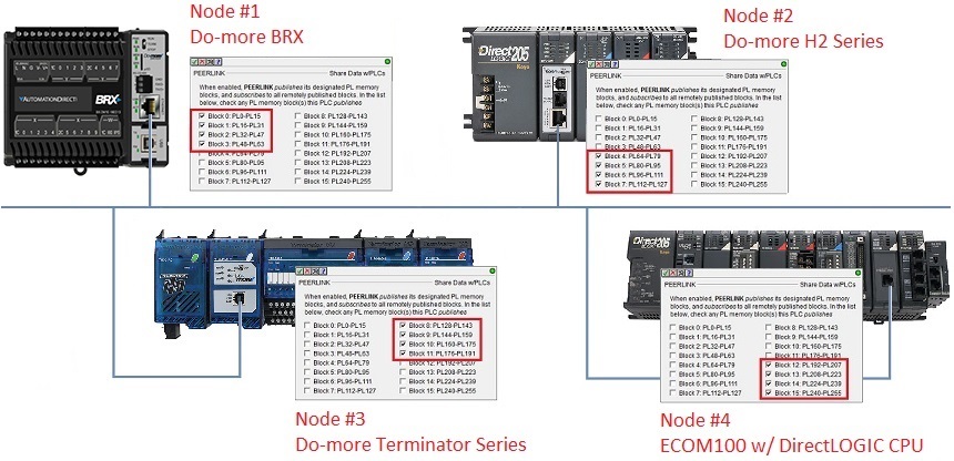
Any of the Do-more CPUs that are equipped with an on-board Ethernet Port can be configured to join a data sharing network that consists of other Do-more PLCs or DirectLOGIC PLC systems using ECOM100 modules. Each member of the data sharing network can send data to the other members of the data sharing network by electing to "publish" one or more of the 16 predefined blocks of PEERLINK (PL) memory. Each member of the data sharing network receives all of the data from all of the other Do-more PLCs and ECOM100s on that data sharing network.
A PEERLINK network uses TCP/IP broadcast packets to publish the
blocks of data to the network. One caveat with the use of broadcast packets
is that it does limit the scope of the shared data network to the local Broadcast Domain![]() A broadcast domain is a logical network segment in which any device connected to the network can directly transmit to any other on the domain without having to go through a routing device. These are typically very basic networks that use hubs rather than switches or routers. A special broadcast address consisting of all 1s is used to send frames to all devices on the network..
A broadcast domain is a logical network segment in which any device connected to the network can directly transmit to any other on the domain without having to go through a routing device. These are typically very basic networks that use hubs rather than switches or routers. A special broadcast address consisting of all 1s is used to send frames to all devices on the network..
Share Data w / PLCs (PEERLINK)
The PEERLINK instruction works with a predefined section of memory named PL. The PL memory contains 256 locations named PL0 through PL255. These 256 locations are divided into 16 blocks. Each of these 16 data blocks consists of 16-Bit unsigned integers. These blocks provide the local storage for the data that is sent and received over the data-sharing network.
In addition to the data blocks, PL memory contains entries for some Bits and Words that are available for use in a ladder program to monitor the runtime status of the PEERLINK network, and to optionally control the updates to individual PEERLINK blocks.
When the input logic to the PEERLINK instruction is ON (the instruction is enabled), at a rate of 10 times per second, the instruction will publish all of the blocks that it is configured to publish, and will process any PEERLINK data blocks that it receives. When the input logic is OFF, (the instruction is disabled), it DOES NOT publish any of its blocks and DOES NOT process any PEERLINK data blocks that it receives.
See ECOM / ECOM100 FAQ #120 for instructions on how to configure ECOM100s to participate in a PEERLINK network.
Communicating with Modbus/TCP Devices
Do-more CPUs equipped with on-board Ethernet ports can communicate with Modbus/TCP Client (Master) and Modbus/TCP Server (Slave) devices on the same Ethernet network.
Modbus/TCP Server
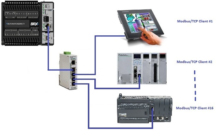
The Modbus/TCP Server in a Do-more CPU can support up to 16 concurrent sessions with Modbus/TCP Clients. The default configuration of a Do-more CPU is for the Modbus/TCP Server to be enabled on TCP/IP port 502. The configuration can be changed in the CPU Configuration section of the System Configuration
Devices that connect to a Do-more CPU using Modbus/TCP protocol will only have access to the following blocks of memory (these blocks are numbered in decimal):
Modbus Inputs
MI0 - MI1023
MC0 - MC1023
MIR0 - MIR2047
MHR0 - MHR2047
Note: The size of the memory blocks available to the Modbus/TCP driver can be changed in the Memory Configuration.
The Modbus/TCP Server (Slave) supports the following function codes:
Description
1
2
3
4
Read input Registers
5
6
7
15
16
22
Mask Write Register
Modbus/TCP Client
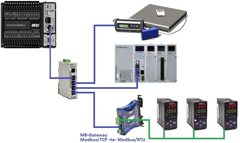
Do-more CPUs can operate as Modbus/TCP Clients (typically to other PLCs) through the use of the following instructions:
Uses Modbus/TCP protocol to read data from a Modbus/TCP Server.
Uses Modbus/TCP protocol to write data to a Modbus/TCP Server.
Note: Modbus/TCP clients require a TCP connection be established to the Modbus/TCP Server before the Modbus communication can take place. If you will be communicating to more than one Modbus/TCP Server (Servers with different IP Addresses) then we recommend that a separate Modbus/TCP Client Device be created for each of the Modbus/TCP Servers. Doing this will minimized the TCP overhead required to manage connections to multiple Modbus/TCP Servers. Any time you use the same Modbus/TCP Client Device for multiple IP Addresses you will see Info Message M240 in the Output Window that will alert you to this condition.
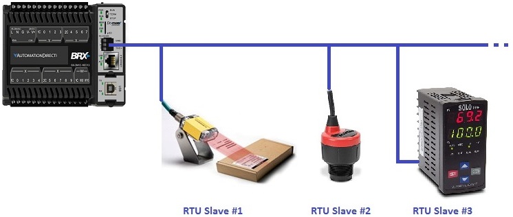
Communicating with Modbus/RTU Devices
The on-board serial port of the Do-more CPU and the ports of SERIO and SERIO-4 modules can be configured to communicate with Modbus/RTU devices.
Modbus/RTU Server
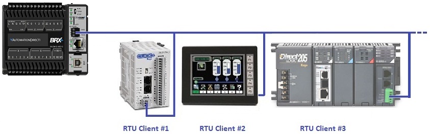
When a serial port is configured this way it will allow third-party client devices that communicate via Modbus/RTU protocol to connect to the serial port.
Devices that connect to a Do-more CPU using Modbus/RTU protocol will only have access to the following blocks of memory (these blocks are numbered in decimal):
Block Name
Description
Default Range
MI
Modbus Inputs
MI0 - MI1023
MC
Modbus Control Relays
MC0 - MC1023
MIR
Modbus Input Registers
MIR0 - MIR2047
MHR
Modbus Holding Registers
MHR0 - MHR2047
Note: The size of the memory blocks available to the Modbus/RTU driver can be changed in the Memory Configuration.
The Modbus/RTU Server (Slave) supports the following function codes:
Function Code
Description
1
Read Coils
2
Read Discrete Inputs
3
Read Holding Registers
4
Read input Registers
5
Write Single Coil
6
Write Single Register
7
Read Exception Status
15
Write Multiple Coils
16
Write Multiple Registers
22
Mask Write Register
Modbus/RTU Client
Uses Modbus/RTU protocol to read data from a Modbus/RTU Slave / Server.
Uses Modbus/RTU protocol to write data to a Modbus/RTU Slave / Server.
Communicating with EtherNet/IP Devices
The EtherNet/IP Server Configuration options are used to setup and optimize the EtherNet/IP Server in PLCs that have an on-board Ethernet port.
EtherNet/IP Explicit Message Server

The EtherNet/IP Server can support up to 16 concurrent sessions with Explicit Unconnected EtherNet/IP Client
An explicit unconnected message client initiates request/response oriented communications with other devices. Message rates and latency requirements are typically not too demanding. Examples of explicit message clients are HMI devices, programming tools, or PC-based applications that gather data from control devices. devices. The default configuration of a Do-more CPU is for the EtherNet/IP Explicit Message Server to be disabled. It can be enabled and configured in the CPU Configuration section of the System Configuration
EtherNet/IP Explicit Message Client

The Send EtherNet/IP Message (EIPMSG) instruction implements an Explicit Unconnected EtherNet/IP Client![]() An explicit unconnected message client initiates request/response oriented communications with other devices. Message rates and latency requirements are typically not too demanding. Examples of explicit message clients are HMI devices, programming tools, or PC-based applications that gather data from control devices. using the on-board Ethernet port of a Do-more CPU. An explicit message client initiates request / response oriented communications with EtherNet/IP servers.
An explicit unconnected message client initiates request/response oriented communications with other devices. Message rates and latency requirements are typically not too demanding. Examples of explicit message clients are HMI devices, programming tools, or PC-based applications that gather data from control devices. using the on-board Ethernet port of a Do-more CPU. An explicit message client initiates request / response oriented communications with EtherNet/IP servers.
EtherNet/IP uses the Common Industrial Protocol (CIP)![]() The Common Industrial Protocol (CIP) is a media independent, connection-based, object-oriented protocol designed for automation applications. It encompasses a comprehensive set of communication services for automation applications: control, safety, synchronization, motion, configuration and information. It allows users to integrate these applications with enterprise-level Ethernet networks and the Internet., a strictly object-oriented protocol, at the upper layers. Each CIP object has attributes (data), services (commands) and behaviors (reactions to events). In the CIP Protocol, every network device represents itself as a series of objects. Each object is simply a grouping of the related data values in a device. Application Objects allow the user to organize the data that are specific to a particular kind of device. These objects define the data encapsulated by the device. They are specific to the device type and function.
The Common Industrial Protocol (CIP) is a media independent, connection-based, object-oriented protocol designed for automation applications. It encompasses a comprehensive set of communication services for automation applications: control, safety, synchronization, motion, configuration and information. It allows users to integrate these applications with enterprise-level Ethernet networks and the Internet., a strictly object-oriented protocol, at the upper layers. Each CIP object has attributes (data), services (commands) and behaviors (reactions to events). In the CIP Protocol, every network device represents itself as a series of objects. Each object is simply a grouping of the related data values in a device. Application Objects allow the user to organize the data that are specific to a particular kind of device. These objects define the data encapsulated by the device. They are specific to the device type and function.
These application layer objects are predefined for a large number of common device types. The same type of CIP devices must contain the same series of application objects. The series of application objects for a particular device type is known as the device profile. Objects not found in the profile for a device class are termed Vendor Specific. These objects are included by the vendor as additional features of the device. The CIP protocol provides access to these vendor extension objects in exactly the same way as either application or required objects. The Send EtherNet/IP Message instruction gains access to these regular pieces of data from the network to the device through an Object (or Class) Number, an Instance Number (Instances are the way of organizing the same kind of data ,e.g., sharing same attributes ), and optionally an Attribute Number.
Send EtherNet/IP Message (EIPMSG)
Send an EtherNet/IP message to an EtherNet/IP Explicit Message Server.
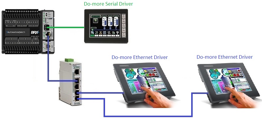
Connecting C-More Panels
C-More™ and C-More Micro™ operator panels can be configured to use either a Do-more Serial driver to connect to a serial port (on-board port or SERIO module), or a Do-more Ethernetdriver to connect to an Ethernet port (on-board port or ECOM100 module) on a Do-more PLC system
Generally speaking, a single Do-more CPU can concurrently service up to 6 of the C-More panels over an Ethernet connection. There are some mechanisms in the panel that can be used to "pace" the communications when multiple panels are connected to the same Do-more CPU which can help to even out the communication throughput and make the individual panels equally responsive.
Outbound Email
The on-board Ethernet Port of a Do-more CPU can be configured to send Email using an SMTP connection from the Do-more CPU to an SMTP server. This requires that you first setup an SMTP Client Device in the Device Configuration which contains all of the information (TCP/IP Address, Authentication, etc.) required to establish the connection to the SMTP Server.
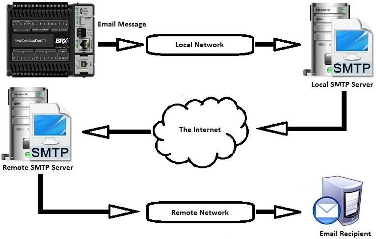
Send an Email message using the specified SMTP Client connection. The Email message can be any combination of text and data elements from the PLC, and can even include an attachment from the PLC File System.
Use the Name to IP Address (DNSLOOKUP), Ping Ethernet Device (PING), and Write Device Register (DEVWRITE) instructions to manage the network connection to the SMTP Server at runtime.
Communicating with an MQTT Broker
BRX PLCs with on-board Ethernet Ports can connect to one or more MQTT Brokers, and once connected, these PLCs can publish messages to the Brokers and subscribe to messages from the Brokers. The parameters required to create connection to a Broker are managed by an MQTT Client (IoT) device.
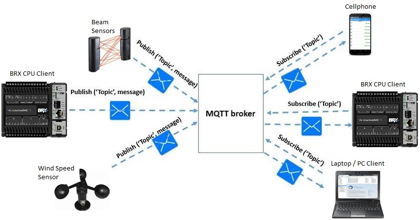
The IoT Publish MQTT Topics (MQTTPUB) instruction is used to publish messages from a BRX CPU to an MQTT Broker.
The IoT Subscribe to MQTT Topics (MQTTSUB) instruction is used to subscribe to Topics in an MQTT Broker.
Communicating the FTP Servers
The on-board Ethernet Port of a Do-more CPU can be configured to send file to and receive files from an FTP server. This requires that you first setup an FTP Client Device in the Device Configuration which contains all of the information (Name, Authentication, etc.) required to establish the connection to the FTP Server.
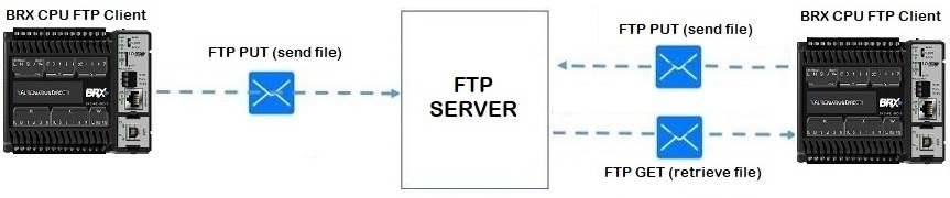
Receive File FROM Remote (FTPGET) instruction is used to retrieve a copy of a file on an FTP server and store the file in one of the BRX CPU's on-board file systems.
Store File TO Remote (FTPPUT) instruction is used to send a copy of a file in one of the BRX CPU's on-board file systems to an FTP server.
Communicating with HTTP Servers
The on-board Ethernet Port of a Do-more CPU can be configured to interact with an HTTP (web) server.
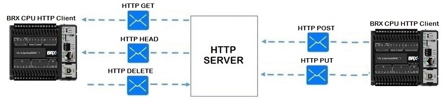
Execute HTTP Command (HTTPCMD) instruction is used to send an HTTP GET, HEAD, POST, PUT, or DELETE command and any required data to a web server.
Communicating with DMX512 Devices
BRX CPU's using a BX-SERIO module can operate as a DMX512 Controller or DMX512 Slave.

For each BX-SERIO port that is configured as either a DMX512 Controller or DMX512 Slave, a memory block of 512 Unsigned Bytes is automatically created, default name is DMXA / DMXB / DMXC / DMXD. There will also be an associated data structure that is automatically created . The structure will be named the same as the aforementioned memory block, the default names are $DMXA / $DMXB / $DMXC / $DMXD. The structure fields can be used in the ladder logic program. The syntax for using them is <structure name>.<field name>, for example: $DMXA.EnableMaster. Each structure contains the following member fields:
.FrameCounter (read-only) is an Unsigned Byte that shows the total number of DMX512 packets that have been received.
.FrameSize (read / write) is an Unsigned Word . If the port is a DMX512 Controller this value sets how many of the 512 bytes to send in the out-gong packet. If the port is a DMX512 Slave this value contains the number of bytes that were received in the last packet.
.EnableMaster (read / write; only applicable if the port is a DMX512 Controller) is a Bit that, when ON, will cause the DMX512 Controller to begin sending packets containing the number of bytes defined in .FrameSize, if OFF, no packets will be sent.
Communication with ASCII Device using a Custom Protocol
Do-more CPUs can communicate with Ethernet or Serial devices that use a custom protocol. These devices send and receive data in one of two ways: the data flows into and out of a data buffer one byte at a time in a continuous manner - we call this streaming data - or the data flows into an out of a data buffer in predefined groups of bytes - we call this packet data.
Stream Devices
To handle data sent to / read from streaming devices over serial ports you must configure the port for General Purpose.
Stream In Data from Device (STREAMIN)
Retrieves the specified number of bytes of data from the input buffer of a stream-capable input device (like a serial port or an Ethernet port) and store that data in either a String (if the data is ASCII text) or a numeric data block (if the data is binary).
Stream Out Data to Device (STREAMOUT)
Sends the specified number of bytes of data from a String or numeric data block to the specified, stream-capable device, such as a serial port or Ethernet port.
Packet Devices
Packet Devices use a predefined UDP Connection to send and receive data over the on-board Ethernet port. The UDP Connection device contains an input buffer that can hold up to 8 packets of 1024 bytes each. Any packets received while the input buffer is full will be discarded.
The data structure associated with each UDP Connection contains a Bit named .PacketAvailable which will be ON any time that the Packet Device's input buffer has a packet ready to be retrieved. This Bit can be used as a trigger for the PACKETIN instruction.
It is important to know that each time this instruction retrieves a packet an entire packet is processed. The specified number of bytes specified in the instruction are copied into specified storage location then the entire packet is purged from the input buffer. Any characters that were NOT read from that packet will be discarded.
Input Data from Packet Device (PACKETIN)
Retrieves a packet of data from the CPU's on-board Ethernet using a predefined UDP Connection and store that data in either a String (if the data is ASCII text) or a numeric data block (if the data is binary).
Output Data to Packet Device (PACKETOUT)
Uses a predefined UDP Connection to send packets of up to 1024 bytes of data from a String or a numeric data block out through the CPU's on-board Ethernet port to a UDP Server.
Communicating with DirectLOGIC CPUs
Do-more CPUs can communicate with legacy DirectLOGIC clients using the K-Sequence protocol over a serial port or a Serial port on a SERIO module,
K-Sequence Server
The on-board serial port or a port on a SERIO module can be configured as a K-Sequence Server in the Module Configuration page of the System Configuration.
DirectLOGIC Client
Do-more CPUs can also use the on-board Ethernet port or an ECOM / ECOM100 module to communicate with a remote DirectLOGIC PLCs that has also an ECOM / ECOM100 module.
DirectLOGIC Network Read (DLRX)
Uses the on board Ethernet port or an ECOM module to read data from a remote DirectLOGIC PLC through an ECOM module in the remote system. This instruction use DirectNET protocol.
DirectLOGIC Network Write (DLWX)
Uses the on-board Ethernet port or an ECOM module to write data to a remote DirectLOGIC PLC through an ECOM module in the remote system. This instruction uses DirectNET protocol.