Topic: DMD0498

EtherNet/IP Server / Adapter Configuration
(Only available on BRX CPUs)
The EtherNet/IP Server / Adapter Configuration setups the EtherNet/IP Server in BRX CPUs that have an on-board Ethernet port or a BX-P-ECOMEX POM. The EtherNet/IP Server can support up to 16 concurrent sessions with Explicit Unconnected EtherNet/IP ClientsAn explicit unconnected message client initiates request/response oriented communications with other devices. Message rates and latency requirements are typically not too demanding. Examples of explicit message clients are HMI devices, programming tools, or PC-based applications that gather data from control devices. and / or Implicit scanners.
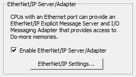
The Enable EtherNet/IP Server / Adapter option completely enables and completely disables the CPU's EtherNet/IP Server / Adapter device driver. If this option is unchecked the CPU will not respond to any EtherNet/IP Client requests. Once this Server has been enabled, runtime status of the EtherNet/IP Server is accessed through the built-in structure $IntEIPServer which has the following members:
.ActiveSessions is the number of concurrent open connections to EtherNet/IP Implicit Scanners.
.LastError is last error reported to an EtherNet/IP client.
.Errors is total number of errors returned to all EtherNet/IP clients.
.Transactions is total number of completed client requests to EtherNet/IP clients.
Once the EtherNet/IP service is enabled, clicking the EtherNet/IP Settings... button will open a dialog to configure the EtherNet/IP Server / Adapter's operating parameters.
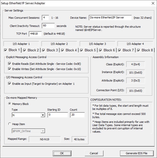
Server Settings are selections that control how the EtherNet/IP Server handles connections from Explicit Message clients and Implicit Scanners :
The Maximum Concurrent Sessions (1 - 16) value specifies how many simultaneous connections from Explicit Message Clients and / or Implicit Scanners the EtherNet/IP Server device driver can handle. Establishing an EtherNet/IP session requires processing time which will inevitably impact the scan time. If there are more EtherNet/IP Clients requesting connections than there are concurrent sessions available, part of this processing includes shutting down the oldest session so that a new session can be opened. The need to forcibly close sessions so that new ones can be opened can be minimized by setting this value to the maximum number of individual EtherNet/IP Clients that will be connecting to this PLC at any given time. This can be any constant value between 1 and 16.
Client Inactivity Timeout (seconds) specifies how much time (in seconds) to wait before closing the connection for a EtherNet/IP Client that has stopped communicating. This can be any constant value between 0 and 65535.
TCP Port Number (44818 is default) specifies which TCP port number the EtherNet/IP Server will accept connections on. The default value of 44818 is the industry standard, and value will rarely need to be changed. This can be any constant value between 0 and 65535.
Device Name will be returned in requests for the Identity Class, it can be up to 32 characters in length.
When Used by EtherNet/IP Explicit Clients
There can be up to 8 Data Blocks made available to EtherNet/IP Explicit Message Clients. This section specifies the which of those 8 data blocks are available, the read and / or write access for each block, and then configures which type and location of the CPU's memory each of the blocks will be mapped to. A Block can be accessible by both an Explicit Message client and an Implicit Scanner.
Check Enable for a block to make it accessible to either the EtherNet/IP Explicit Message Clients.
Explicit Message Access Control options define how the block can be accessed externally by an Explicit Message client:
Check Enable Reads (Get Single Attribute - Service Code: 0x0E) to allow read access to this data block using Get Single Attribute.
Check Enable Writes (Set Single Attribute - Service Code: 0x10) to allow write access to this data block using Set Single Attribute.
Assembly Information displays the Path (class / instance / attribute) of the Block being configured. Fields marked as (Explicit) will be used by a Explicit Message Client to access this Block.
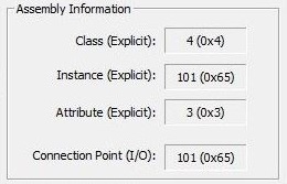
The Class (Explicit) for all 8 of these Blocks is fixed at 0x04.
Instance (Explicit) shows the unique Instance ID value that is used to access this Block:
Instance ID
1
101 (0x65)
2
102 (0x66)
3
103 (0x67)
4
104 (0x68)
5
105 (0x69)
6
106 (0x6A)
7
107 (0x6B)
8
108 (0x6C)
The Attribute (Explicit) for all 8 of these data blocks is fixed at 0x03.
When Used by EtherNet/IP Implicit Scanners
There are 4 available I/O Adapters. Each of the 4 I/O Adapters consumes two of the 8 available blocks. The first block for each I/O Adapter is the Input (Target -> Originator), the second block is the Output (Originator to Target).
I/O Messaging Access Control options define how the selected blocks can be accessed by an Implicit Scanner:
Enable as Input (Target to Originator) on Adapter x will allow read access to this block by Implicit Scanners.
Enable as Output (Originator to Target) on Adapter x will allow write access to this block by Implicit Scanners.
If the I/O Adapter is enabled as an Output, O2T data state on network error determines the state of the contents of the block if the Implicit Scanner loses its network connection to this adapter:
Hold last will leave the contents of the data block or heap item untouched.
Clear will set all of the contents of the data block or the fields of the heap item to 0.
Assembly Information displays the Path (Connection Point) of the Block being configured.
Connection Point (I/O) shows the unique Connection Point values that will be used by an Implicit Scanner to access a Block or other I/O.
Block Number
Connection Point
1
101 (0x65)
2
102 (0x66)
3
103 (0x67)
4
104 (0x68)
5
105 (0x69)
6
106 (0x6A)
7
107 (0x6B)
8
108 (0x6C)
Input Only Heartbeat
238 (0xEE)
Do-more Mapped Memory specifies the memory location that contains the data that will be accessed when requests for this Block's Class / Instance / Attribute / Connection Point are received.
Select Memory Block if this Block's data resides in one of the predefined Numeric or Bit memory blocks.
Element Type, Starting ID, and Countselect which memory block to use, the offset into that block, and how much of that block to use respectively. The maximum total size of an EtherNet/IP request is 500 bytes, so the maximum number of elements per block will depend on the size of the individual elements of that block. Refer to the chart below:
Element Type
Bit
4000
Byte
500
Word
250
DWord
125
Real
125
Select Heap Item if this Block's data resides in a Heap Item. The primary use of this selection is with User Data Types. Select one of the existing Heap Items from the drop-down list of available Heap Items.
The Mapped Range & Size fields display the currently selected range of Elements the size of the selected Element range in Bytes.
Click OK to save the configuration changes that have been made and return to the main CPU Configuration, or Cancel to discard any changes that have been made and return to the main CPU Configuration.
Click the Generate EDS File button to create an EDS (Electronic Data Sheet) file that is appropriate for the Blocks that are enabled and the configuration of those blocks.
EtherNet/IP Supported Paths
The EtherNet/IP Explicit Message Server supports the following Paths: (Class / Instance / Attribute)
|
Class |
Instance |
Attribute |
|
|
0x01 - Identity |
1 |
1 |
Vendor ID |
| 2 |
Device Type |
||
|
3 |
Product Code |
||
|
4 |
Revision |
||
|
6 |
|||
|
7 |
|||
|
0x04 - Assembly |
101 (0x65) |
3 |
Data Block 1 |
|
102 (0x66) |
3 |
Data Block 2 |
|
|
103 (0x67) |
3 |
Data Block 3 |
|
|
104 (0x68) |
3 |
Data Block 4 |
|
|
105 (0x69) |
3 |
Data Block 5 |
|
|
106 (0x6A) |
3 |
Data Block 6 |
|
|
107 (0x6B) |
3 |
Data Block 7 |
|
|
108 (0x6C) |
3 |
Data Block 8 |
|
|
0xF5 - TCP/IP |
1 |
1 |
Status |
|
3 |
Configuration Control |
||
|
3 |
Product Code |
||
|
4 |
|||
|
5 |
Interface Configuration |
||
|
0xF6 - Ethernet Link |
1 |
2 |
Interface Flags |
|
3 |
Physical Address |
EtherNet/IP Error Codes
The following charts show the error responses that will be returned by the EtherNet/IP Server / Adapter:
|
CIP Level Errors
Error Code |
Extended Error Info |
Description |
|
0 (0x00) |
None |
No Error.
|
|
1 (0x01) |
262 (0x106) |
Connection Error is returned during the Forward Open if the user is attempting to open an output instance already opened by another user. Most likely there's is an existing exclusive owner has already configured a connection to this Connection Point. Check to see if other Scanner devices are connected to this adapter.
|
|
1 (0x01) |
264 (0x108) |
Connection Error is returned during the Forward Open if the user didn’t specify at least one instance (input or output). This error occurs when one of the parameters specified in the Forward Open message is not supported such as Connection Point, Connection type, Connection priority, redundant owner or exclusive owner.
|
|
1 (0x01) |
295 (0x127) |
Connection Error is returned during the Forward Open if the user specified an invalid length for the O2T instance. This error is returned when the Originator to Target (Output data) size specified in the Forward Open does not match what is in the Target. Consult the Do-more Mapped Memory setup to verify the required size.
|
|
1 (0x01) |
296 (0x128) |
Connection Error is returned during the Forward Open if the user specified an invalid length for the T2O instance. This error is returned when the Target to Originator (Input data) size specified in the Forward Open does not match what is in Target. Consult the Do-more Mapped Memory setup to verify the required size.
|
|
2 (0x02) |
None |
Resource Unavailable is returned if the Target device does not have the resources to process the Unconnected Send request.
|
|
3 (0x03) |
None |
Invalid Parameter is returned if one of the parameters specified in the Forward Open is not valid.
|
|
4 (0x04) |
None |
Bad Path Segment is returned if path segment is improperly formed.
|
|
5 (0x05) |
None |
Path Unknown is returned for any unknown path (class / instance / attribute).
|
|
8 (0x08) |
None |
Unsupported Service is returned for any unsupported service.
|
|
19 (0x13) |
None |
Not Enough Data is returned when using SetAttributeSingle (16, 0x10) if the data length is too short.
|
|
21 (0x15) |
None |
Too Much Data is returned when using SetAttributeSingle (16, 0x10 if the data length is too long.
|
See Also:
EtherNet/IP Server / Adapter Configuration
Ethernet I/O Master Configuration
Related Topics:
EIPMSG - Send EtherNet/IP Message