DMD0527

CTREGWR - CTRIO Write Register
The CTRIO Write Register (CTREGWR) instruction is used to write values from locations in the Do-more CPU to the selected internal registers of the CTRIO. The CTREGWR instruction can be used with both the CTRIO and CTRIO2 modules.
Parameters:
Note: Use the F9 key or click the 'three dot box' at the right edge of the parameter field to open the Default Element Selection Tool (the Element Picker or the Element Browser) or use the Down-Arrow key (Auto-Complete) on any parameter field to see a complete list of the memory locations that are valid for that parameter of the instruction.
Module selects which CTRIO module to use.
create module will open the Create New Module Configuration dialog where a CTRIO Module can be created.
Module Structure is the name of the Module structure that will be used by this instruction. This structure was created when the CTRIO module was setup during the Module Configuration phase.
Source - specifies the location to store the value read from the CTRIO module. This can be any 32-bit readable numeric location.
Destination Register - selects which of the following internal registers to write:
-
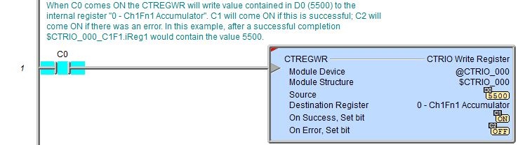
0 - Ch1Fn1 Accumulator: Channel 1 Function 1 raw count value (e.g. .iReg1 if Ch1Fn1 is unscaled or .iReg2 if Ch1Fn1 is scaled).
-
1 - Ch1Fn2 Accumulator: Channel 1 Function 2 raw count value (e.g. .iReg1 if Ch1Fn2 is unscaled or .iReg2 if Ch1Fn2 is scaled).
-
2 - Ch2Fn1 Accumulator: Channel 2 Function 1 raw count value (e.g. .iReg1 if Ch2Fn1 is unscaled or .iReg2 if Ch2Fn1 is scaled).
-
3 - Ch2Fn2 Accumulator: Channel 2 Function 2 raw count value (e.g. .iReg1 if Ch2Fn2 is unscaled or .iReg2 if Ch2Fn2 is scaled).
-
5 - Out 1 Position: Output 1's position value.
-
6 - Out 2 Position: Output 2's position value.
-
7 - Out 3 Position: Output 3's position value.
-
8 - Ch1Fn1 Reset Value: The value Channel 1 Function 1 accumulator will be set to when the reset bit (e.g. $CTRIO_000_C1F1.Reset) is subsequently set ON, or a subsequent external reset on the CTRIO input is detected (if configured as such).
-
9 - Ch1Fn2 Reset Value: The value Channel 1 Function 2 accumulator will be set to when the reset bit (e.g. $CTRIO_000_C1F2.Reset) is subsequently set ON, or a subsequent external reset on the CTRIO input is detected (if configured as such).
-
10 - Ch2Fn1 Reset Value: The value Channel 2 Function 1 accumulator will be set to when the reset bit (e.g. $CTRIO_000_C2F1.Reset) is subsequently set ON, or a subsequent external reset on the CTRIO input is detected (if configured as such).
-
11 - Ch2Fn2 Reset Value: The value Channel 2 Function 2 accumulator will be set to when the reset bit (e.g. $CTRIO_000_C2F2.Reset) is subsequently set ON, or a subsequent external reset on the CTRIO input is detected (if configured as such).
-
12 - Ch1A Filter Time (CTRIO2): Software noise filter value in nanoseconds for Channel 1 Input A (for full explanation see here).
-
13 - Ch1B Filter Time (CTRIO2): Software noise filter value in nanoseconds for Channel 1 Input B (for full explanation see here).
-
14 - Ch1C Filter Time (CTRIO2): Software noise filter value in nanoseconds for Channel 1 Input C (for full explanation see here).
-
15 - Ch1D Filter Time (CTRIO2): Software noise filter value in nanoseconds for Channel 1 Input D (for full explanation see here).
-
16 - Ch2A Filter Time (CTRIO2): Software noise filter value in nanoseconds for Channel 2 Input A (for full explanation see here).
-
17 - Ch2B Filter Time (CTRIO2): Software noise filter value in nanoseconds for Channel 2 Input B (for full explanation see here).
-
18 - Ch2C Filter Time (CTRIO2): Software noise filter value in nanoseconds for Channel 2 Input C (for full explanation see here).
-
19 - Ch2D Filter Time (CTRIO2): Software noise filter value in nanoseconds for Channel 2 Input D (for full explanation see here).
The On Success and On Error parameters specify what action to perform when this instruction completes. You do not have to use the same type of selection for both On Success and On Error.
If the Set Bit selection is used for either On Success or On Error, the specified BIT location will be SET OFF when the instruction is first enabled and will remain OFF until the instruction completes. Once complete, the appropriate Success or Error bit location ON. The specified Bit location is enabled with a SET (Latch) operation meaning that it will remain ON even if the input logic for the instruction goes OFF.
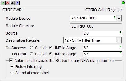
If the JMP to Stage selection is used for either On Success or On Error the target Stage must be in the same Program code-block as this instruction, you cannot specify a target Stage that exists in a different Program code-block. When the operation finishes, the target Stage will be enabled the same way as a standalone Jump to Stage (JMP) instruction would do it. The JMP to Stage option will only be available if this instruction is placed in a Program code-block.
On Success selects which of the following actions to perform if the operation is successful:
- Enable SET Bit then specify any writable bit location.
- Enable JMP to Stage then specify any
Stage number from S0 to S127 in the current Program code-block.
On Error selects which of
the following actions to perform if the operation is unsuccessful:
- Enable SET Bit then specify writable bit location.
- Enable JMP to Stage then specify any Stage number from S0 to S127 in the current Program code-block.
If either the On Success or On Error selections are set to JMP to Stage, Automatically create the SG box for any NEW stage number will be enabled which will automatically create any target stage that does not already exist.
- Below this rung will create the new target stage on a new rung following this instruction.
- At end of code-block will create the new target stage as the last rung of this Program.
Note: any time the On Error condition occurs, the CTRIO generates an Error Code that can be read in the <Module Name>.ErrorCode (Module Name is the name assigned to the CTRIO in the Module Configuration). The List of Error Code values (in decimal) follows:
Status Display:
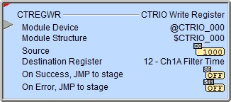
The status display of the instruction shows Values: Source.
The red triangle in the upper left corner of the status display indicates this is a Fully Asynchronous instruction.
The gray triangle at the right end of the input leg indicates the input is edge-triggered, meaning this instruction will execute each time the input logic transitions from OFF to ON.
See Also:
CTDYNPOS - CTRIO Run Dynamic Position Mode
CTDYNVEL - CTRIO Run Dynamic Velocity Mode
CTPLSADD - CTRIO2 Add Entry to PLS
CTPLSEDT - CTRIO2 Edit PLS Entry
CTREGWR - CTRIO Write Register
CTRUNPOS - CTRIO Run Position Mode
CTRUNVEL - CTRIO Run Velocity Mode
CTTBLADD - CTRIO Add Entry to Preset Table
CTTBLEDT - CTRIO Edit Preset Table Entry
Example 1 of 2:
Description of a Typical CTRIO Write Register (CTREGWR) Stage Diagram:
This is a stage diagram of a simple sequence control that would move a motor to any number of positions. But it has a feature of remembering the position of the motor in case there is a power cycle. The output position is stored in a retentive memory location and then written back.
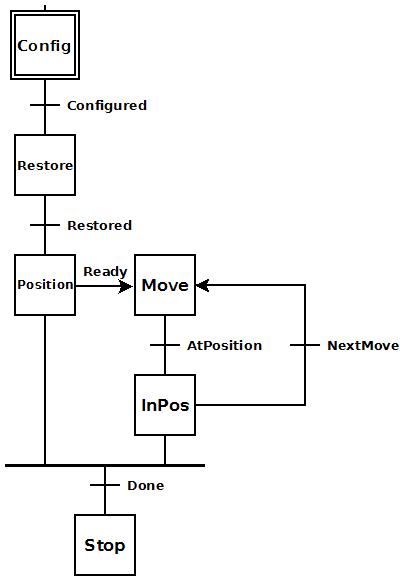
Initially the Config stage sets the CTRIO2 axis up. Once this is configured it transitions to the Restore stage.
The Restore stage reads the retentive location where the output position was stored previously and writes it back to the CTRIO2 module. Once this is restored it transitions to the Position stage.
The Position stage puts the CTRIO2 pulse output into the Dynamic Position mode. Once this is complete (Ready = ON) then the Move stage is enabled (not transitioned to) so that both stages are running in parallel. The reason for this is because the Position stage must be left enabled to keep the CTRIO2 pulse output in the Dynamic Position mode through all the moves. Also inside this stage the current output position is continuously updating the retentive location in case of power failure.
Once the CTRIO pulse output has reached its new position (AtPosition = ON), then it transitions to the InPos stage.
In the InPos stage another position can be loaded and then the NextMove can be set ON to transition back to the Move stage to move the motor to another position, or the Done button can be set ON to finish things up. If Done is set ON, then both the Position and InPos (In Position) stages converge and transition to the Stop stage.
Description of a Typical CTRIO Write Register (CTREGWR) Stage Ladder:
This is the ladder equivalent of the above stage diagram that uses the CTREGWR instruction to restore the output position of the CTRIO2 module after a power cycle. It only works for a CTRIO2 since the CTAXCFG instruction cannot be used with a CTRIO.
Note: Even though the output position structure member (.OutputPosition) is retentive, the CTRIO2 itself, on a power up, clears this value to zero.
This example presupposes the use of a CTRIO2 (instead of a CTRIO) module and the existence of the following System Configuration for the CTRIO2 (PLC --> System Configuration --> Module Configuration(s) --> CTRIO_000 -->):
-
A stepper motor is wired to CTRIO2's Output 0 and Output 1.

The general operation of this example is to configure a CTRIO2 axis using the CTAXCFG (CTRIO2 Axis Configuration) instruction (for more information click here), restore the output position of the CTRIO2 using the CTREGWR (CTRIO Write Register) instruction, and then to enable the CTAXDYNP (CTRIO2 Axis Run Dynamic Position Mode) instruction (for more information click here) and allow moves to any number of positions provided by HMI_Position variable while storing the CTRIO2's output position in a retentive memory location (CurrentPosition) in the Do-more controller.
Config is the initial stage and configures an axis in the CTRIO2. When this is completed without error it transitions to the Restore stage. If there is an error it transitions to the ErrorStage stage where logic (not shown here) should exist that would properly handle the error (e.g. to process the $CTRIO_000.ErrorCode value).
Restore stage writes the contents of the CurrentPosition memory location to the 4 - Out0 Position register in the CTRIO2. This CurrentPosition variable will contain the last output position of the CTRIO2 output that this same Program code block provided from a previous run. If this is the first time this Program code block has been run, then this will simply write a value of 0 to this internal register which is harmless because the CTRIO2 will have already zeroed-out this register on power up any way. This stage also sets Begin ON to enable the CTAXDYNP in the Position stage. When the CTREGWR instruction completes without error it transitions to the Position stage. If there is an error it transitions to the ErrorStage stage.
Position is the main CTAXDYNP instruction stage. Upon the first entry into this stage the CurrentPosition is moved to the HMI_Position. This is done so that the CTAXDYNP will not move if HMI_Position happens to have a wrong value in it. Notice that for every scan of this stage the CTRIO2's output position ($CTRIO_000_Out0.OutputPosition) is stored in the memory location CurrentPosition.
This stage remains enabled for all moves. Instead of transitioning to the next stage (Move), the next stage is merely enabled. Begin is already ON when first entering this stage and will enable the CTAXDYNP instruction. Then the following things occur:
-
The Pulse Output Device ($CTRIO_000_Out0) will be placed in the "Dynamic Position Mode."
-
The current position value (internal to CTRIO2) is left intact because of the setting of Current Position parameter to "Maintain value".
-
The CTRIO2's Pulse Output is enabled ($CTRIO_000_Out0.OutputEnabled = ON).
The Begin bit will remain ON for all moves. It will be cleared OFF at the completion of the last move.
The CTAXDYNP's SUS (Suspend) input is controlled by the Suspend bit. This bit must remain OFF for any given move to complete. Turning this bit ON will cause the CTRIO2's output to decelerate to a stop. Turning it back OFF will cause the CTRIO2's output to accelerate complete a move.
The On Success parameter jumps to the Stop stage. This will occur when Begin is cleared OFF and everything was successful.
The On Error parameter jumps to the ErrorStage stage
Once the CTAXDYNP is enabled, the $CTRIO_000_Out0.OutputEnabled bit will be set ON by the Pulse Output Device. When this occurs the next stage (Move) is enabled.
Move stage accomplishes the first move and any subsequent moves. Initially it is assumed a new position has been written to the HMI_Position variable. To move, the $CTRIO_000_Out0.GotoPosition bit is set ON. The Pulse Output Device will clear this bit when the move begins. Once the bit is cleared, then the $CTRIO_000_Out0.AtPosition bit is monitored for completion of the move. Once that bit is set ON by the Pulse Output Device, this move is complete and the Move stage transitions to the InPos stage.
The InPos stage turns ON Positioned to indicate the position has been reached. This is the ideal spot in the Program code block for a power loss. The reason-being that CurrentPosition will definitely contain the last output position because it has just been reached. If power is lost during a move, then it is possible that the motor attached to the CTRIO2 may drift from the last recorded output position. In such a case restoring the output position in the manner that this Program code block does may not be sufficient for the application. Instead, the application may demand that the output position be re-homed. This Program code block does not provide that homing sequence.
This stage waits for either the NextMove bit or the Done bit to be toggled ON. It is assumed these bits are momentary contacts. If another position is desired, then HMI_Position is provided a new value and the NextMove bit is toggled. When NextMove bit comes ON the InPos stage transitions back to the Move stage. If this is the last move, then the Done bit is toggled. When Done comes ON then Begin bit is cleared OFF and InPos stage disables itself (SGRST). When the InPos stage is transitioned out of, it will turn the Positioned bit OFF to indicate another move is in progress or all moves are complete.
The Begin bit resets the CTAXDYNP instruction in the Position stage above. This causes the following to happen:
-
The CurrentPosition variable will contain the last output position.
-
The CTRIO2 pulse output is disabled ($CTRIO_000_Out0.OutputEnabled = OFF).
-
The On Success transitions to the Stop stage.
The Stop stage merely exits this Program code block.
Example 2 of 2: