DMD0518

CTPLSADD - CTRIO2 Add Entry to PLS
Note: The CTPLSADD instruction can only be used with the CTRIO2 modules.
The CTRIO2 Add Entry to PLS (CTPLSADD) instruction is used to add an entry to a PLS table that is currently loaded for the specified CTRIO2 Discrete Output or create a new PLS on-the-fly and add the first entry. Entries in the PLS table must be sorted into numerical order. At the conclusion of the Add PLS Entry process, the CTRIO2 will resort the PLS table. This could result in entry Numbers moving within the PLS table.
Changes made to CTRIO Preset tables using this instruction do not change any of the Preset tables that were configured in the Module Configuration for the CTRIO. They are temporary and are lost on a power-cycle of the CTRIO or if some other table is loaded in their place. The changes made by this instruction cannot be viewed in the Module Configuration.

Parameters:
Note: Use the F9 key or click the 'three dot box' at the right edge of the parameter field to open the Default Element Selection Tool (the Element Picker or the Element Browser) or use the Down-Arrow key (Auto-Complete) on any parameter field to see a complete list of the memory locations that are valid for that parameter of the instruction.
Discrete Output Device selects which preconfigured CTRIO Discrete Output device to use. Before this instruction can select a Discrete Output device, a CTRIO Device must be configured with at least one of its output channels setup for Discrete output mode.
no devices available indicates that there are no CTRIO Discrete Output devices that have been configured that can perform this instruction.
create module will open the Create New Module Configuration dialog where a CTRIO Module can be created and then a CTRIO Discrete Output device can then be configured.
Discrete Output Structure is the name of the Discrete Output structure that will be used by this instruction. This structure was created when the CTRIO module configuration was read during the Module Configuration phase.
Initialize First enable this option to clear any entries in the currently loaded PLS table before adding the preset specified in this instruction.
Initial Output State (only valid with Initialize First) selects the initial state of the output, either ON or OFF.
Output ON when Greater than or Equal to is the beginning pulse count of the next Limit position in the PLS table. The Output will be ON when the count value is greater than or equal to this value. This can be any constant value, or any readable numeric location.
AND Less Than is the ending pulse count of the next Limit position in the PLS table. The Output will be OFF when the count value is less than this value. This can be any constant value, or any readable numeric location.
The On Success and On Error parameters specify what action to perform when this instruction completes. You do not have to use the same type of selection for both On Success and On Error.
If the Set Bit selection is used for either On Success or On Error, the specified BIT location will be SET OFF when the instruction is first enabled and will remain OFF until the instruction completes. Once complete, the appropriate Success or Error bit location ON. The specified Bit location is enabled with a SET (Latch) operation meaning that it will remain ON even if the input logic for the instruction goes OFF.
If the JMP to Stage selection is used for either On Success or On Error the target Stage must be in the same Program code-block as this instruction, you cannot specify a target Stage that exists in a different Program code-block. When the operation finishes, the target Stage will be enabled the same way as a standalone Jump to Stage (JMP) instruction would do it. The JMP to Stage option will only be available if this instruction is placed in a Program code-block.
On Success selects which of the following actions to perform if the operation is successful:
- Enable SET Bit then specify any writable bit location.
- Enable JMP to Stage then specify any
Stage number from S0 to S127 in the current Program code-block.
On Error selects which of
the following actions to perform if the operation is unsuccessful:
- Enable SET Bit then specify writable bit location.
- Enable JMP to Stage then specify any Stage number from S0 to S127 in the current Program code-block.
If either the On Success or On Error selections are set to JMP to Stage, Automatically create the SG box for any NEW stage number will be enabled which will automatically create any target stage that does not already exist.
- Below this rung will create the new target stage on a new rung following this instruction.
- At end of code-block will create the new target stage as the last rung of this Program.
Note: any time the On Error condition occurs, the CTRIO generates an Error Code that can be read in the <Module Name>.ErrorCode (Module Name is the name assigned to the CTRIO in the Module Configuration). The List of Error Code values (in decimal) follows:
Status Display:
The Status display of the instruction shows the Values: Greater than or equal to, and AND less than, and the Highlights: .OutputEnabled bit.
The red triangle in the upper left corner of the status display indicates this is a Fully Asynchronous instruction.
The gray triangle at the right end of an input leg indicates the input is edge triggered, meaning that each time the input logic transitions from OFF to ON the instruction will run one time to completion.

CTRIO2 Structure Field Care-Abouts:
The following is a list of the"dot" fields of the CTRIO2 structure that are programmatically used with the CTRIO2 Add Entry to PLS (CTPLSADD) instruction. To see a complete listing of all CTRIO structures and members, go to the Project Browser --> Configuration --> Memory --> I/O --> Specialty.
COLOR KEY
Blue: CTRIO Input
Maroon: CTRIO Output
Black: CTRIO Module
Silver: Not used for this instruction
Note: The red "x" is the digit 0, 1, 2, or 3.
NOTES:
(1)This structure member only available for CTRIO2 (not CTRIO). For CTRIO this remains zero.
See Also:
CTDYNPOS - CTRIO Run Dynamic Position Mode
CTDYNVEL - CTRIO Run Dynamic Velocity Mode
CTPLSADD - CTRIO2 Add Entry to PLS
CTPLSEDT - CTRIO2 Edit PLS Entry
CTREGWR - CTRIO Write Register
CTRUNPOS - CTRIO Run Position Mode
CTRUNVEL - CTRIO Run Velocity Mode
CTTBLADD - CTRIO Add Entry to Preset Table
CTTBLEDT - CTRIO Edit Preset Table Entry
Example 1 of 2:
Description of a Typical CTRIO2 Add Entry to PLS (CTPLSADD) Stage Diagram:
This is a stage diagram of a stage that will all the adding of any number of entries to either an existing PLS table or a newly created one.
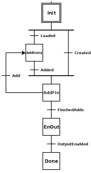
In the Init stage the decision is made as to whether to create a new PLS table on-the-fly, or load a pre-existing one. Before the decision is made the parameters for the entry must be prepared (a lower limit value and an upper limit value). Then, if create is chosen, one is created and transition is made to the AddFin stage. If a pre-existing one is chosen, then it is loaded and transition is made to the AddEntry stage.
The AddEntry adds an entry (with the prepared lower limit and upper limit values) and when finished transitions to the AddFin stage.
In the AddFin stage the decision is made as to whether this was the last entry or to add another one. If another one is desired the lower limit and upper limit values must be prepared and then transition is made back to the AddEntry stage. If this was the last entry, then transition is made to the EnOut stage.
The EnOut stage enables the CTRIO2 discrete output for use with the table and then transitions to the Done stage.
The Done stage exists this Program code block.
Description of a Typical CTRIO2 Add Entry to PLS (CTPLSADD) Stage Ladder:
This is the ladder equivalent of the above stage diagram that uses the CTPLSADD instruction to create and/or add any number of entries to either a pre-existing PLS table or a newly created one.
This example presupposes the existence of the following System Configuration for the CTRIO2 (PLC --> System Configuration --> Module Configuration(s) --> CTRIO_000 -->):
-
Configure I/O -->
-
Discrete Tables --> Add PLS Table (CTRIO2): with the following parameters:
File Number: 9
Name: PLS
Scales: Unscaled
Default Output State: Off
Entry: ON when >= 2500 counts and < 7500 counts. -
A quadrature encoder is wired to CTRIO2's Channel 1 Input A & B.
-
A discrete device that utilizes the CTRIO2's Output is wired to CTRIO2's Output 2.
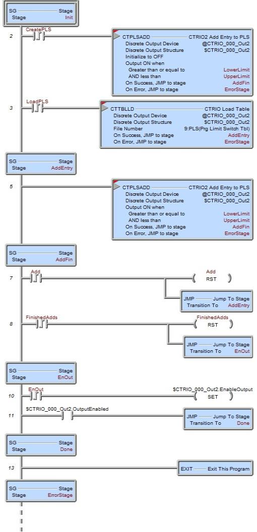
In the Init stage the decision is made whether to create a PLS table on-the-fly or load a pre-existing one. Before making this decision the LowerLimit and UpperLimit values should be prepared. Once these values are set then if CreatePLS is turned ON the CTPLSADD instruction will execute and create a new temporary PLS table complete with its first entry for $CTRIO_000_Out2 because of the parameter Initialize to OFF with the Greater than or equal to value of LowerLimit and the AND less than value of UpperLimit and then, if successful, transition to the AddFin stage. If LoadPLS is turned ON instead, then then CTTBLLD instruction (for more information on this instruction click here) will load a the preexisting PLS table "9:PLS(Prg Limit Switch Tbl)" for $CTRIO_000_Out2 and if successful will transition to the AddEntry stage where the new entry will be added.
If either the CTPLSADD or the CTTBLLD instructions get errors then transition is immediately made to the ErrorStage where logic (not shown here) should exist to properly handle and report the error code now stored in $CTRIO_000.ErrorCode.
Note: The newly created PLS table nor any new entry in a pre-existing PLS table are permanently stored in the CTRIO2 configuration. They are temporary and are lost on a power-cycle of the CTRIO2 or if some other table is loaded in their place. The changes cannot be viewed, for example, in the PLC --> System Configuration.
The AddEntry stage executes the CTPLSADD instruction to add a new temporary PLS entry to either the newly created PLS or a pre-existing PLS. If successful transition is made to the AddFin stage. If there is an error transition is made to the ErrorStage.
In the AddFin stage the decision is made whether to add another entry to the PLS table or finish the adds. If it is decided that another entry is required then the LowerLimit and UpperLimit values should first be prepared and then the Add bit turned ON. If Add bit is turned ON this will reset itself (in preparation for another possible entry) and transition to the AddEntry to do the work. If it did not reset itself then it would be left ON and this would cause the process to oscillate between the AddEntry and AddFin stages. If this was the last entry to be added, then the FinishedAdds bit is turned ON. This bit resets itself and transitions to the EnOut stage where the CTRIO2's output will be enabled for use with the new PLS table.
The EnOut stage sets the $CTRIO_000_Out2.EnableOutput bit and waits for the feedback bit ($CTRIO_000_Out2.OutputEnabled) to come ON. When it does transition is made to the Done stage.
The Done stage exists this Program code block.
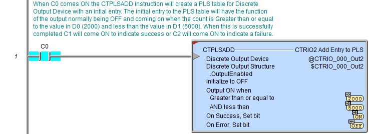
Example 2 of 2: