DMD0529

CTRUNPOS - CTRIO Run Position Mode
The CTRIO Run Position Mode (CTRUNPOS) instruction is used to load and run one of the preconfigured Pulse Profiles in the System Configuration for the CTRIO. The CTRUNPOS instruction can be used with both the CTRIO and CTRIO2 module.

Parameters:
Note: Use the F9 key or click the 'three dot box' at the right edge of the parameter field to open the Default Element Selection Tool (the Element Picker or the Element Browser) or use the Down-Arrow key (Auto-Complete) on any parameter field to see a complete list of the memory locations that are valid for that parameter of the instruction.
Pulse Output Device - selects which preconfigured CTRIO Pulse Output device to use. Before this instruction can select a Pulse Output device, a CTRIO Device must be configured with at least one of its output channels setup for Pulse / Direction or CW / CCW pulse output mode.
no devices available - indicates that there are no CTRIO Pulse Output devices that have been configured that can perform this instruction.
create module - will open the Create New Module Configuration dialog where a CTRIO Module can be created and then a CTRIO Pulse Output device can then be configured.
Pulse Output Structure - this field displays the name of the Pulse Output Structure that will be used by this instruction. This structure was created when the CTRIO module was configured during the Module Configuration phase.
Position File Number - specifies which of the preconfigured Pulse Profiles to Run.
-
Fixed File - displays a list of the preconfigured Pulse Profiles that were read from the CTRIO module during the Module Configuration phase. Select the desired profile from the list. Available Profiles:
PROFILE
(Silver text indicates the profile cannot be used with CTRUNPOS)
CTRIO
CTRIO2
Yes
Yes
Yes
Yes
Yes
Yes
Dynamic Positioning
Yes
Yes
Yes
Yes
Dynamic Positioning Plus (CTRIO2)
Trapezoid Plus (CTRIO2)
No
Yes
No
Yes
-
Variable File Number - specifies a memory location where the Pulse Profile number resides. This can be any readable numeric location.
Optional Target Position (this parameter can only be used with a Trapezoid Plus or the Trapezoid w / Limits profile in the CTRIO2 module) - specifies the target position count value. This can be any positive or negative constant value or any readable numeric location. If this parameter is greater than the current position (.OutputPosition), pulses for a clockwise move are emitted. If this parameter is less than the current position (.OutputPosition), pulses for a counter-clockwise move are emitted.
The On Success and On Error parameters specify what action to perform when this instruction completes. You do not have to use the same type of selection for both On Success and On Error.
If the Set Bit selection is used for either On Success or On Error, the specified BIT location will be SET OFF when the instruction is first enabled and will remain OFF until the instruction completes. Once complete, the appropriate Success or Error bit location ON. The specified Bit location is enabled with a SET (Latch) operation meaning that it will remain ON even if the input logic for the instruction goes OFF.
If the JMP to Stage selection is used for either On Success or On Error the target Stage must be in the same Program code-block as this instruction, you cannot specify a target Stage that exists in a different Program code-block. When the operation finishes, the target Stage will be enabled the same way as a standalone Jump to Stage (JMP) instruction would do it. The JMP to Stage option will only be available if this instruction is placed in a Program code-block.
On Success selects which of the following actions to perform if the operation is successful:
- Enable SET Bit then specify any writable bit location.
- Enable JMP to Stage then specify any
Stage number from S0 to S127 in the current Program code-block.
On Error selects which of
the following actions to perform if the operation is unsuccessful:
- Enable SET Bit then specify writable bit location.
- Enable JMP to Stage then specify any Stage number from S0 to S127 in the current Program code-block.
If either the On Success or On Error selections are set to JMP to Stage, Automatically create the SG box for any NEW stage number will be enabled which will automatically create any target stage that does not already exist.
- Below this rung will create the new target stage on a new rung following this instruction.
- At end of code-block will create the new target stage as the last rung of this Program.
Note: any time the On Error condition occurs, the CTRIO generates an Error Code that can be read in the <Module Name>.ErrorCode (Module Name is the name assigned to the CTRIO in the Module Configuration). The List of Error Code values (in decimal) follows:
Instruction Inputs:

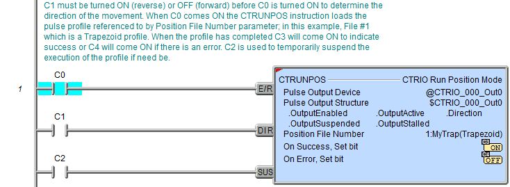
The first input (E/R) in the Enable / Reset input. When this input logic is ON the specified Pulse Profile will be loaded, and the Output will be enabled (.OutputEnabled = ON) and the move will be executed.
The second input (DIR) is the Direction. This input has different effects on the CTRIO output depending on the pulse profile specified by the Position File Number parameter.
| DEVICE |
CTRIO/CTRIO2 PULSE PROFILE |
EFFECT |
| CTRIO2 |
Trapezoid
|
If the DIR
input is OFF when the E/R input
comes ON, the CTRIO2 will generate pulses for clockwise (positive) direction. |
|
Trapezoid Plus (CTRIO2) |
The DIR
input has no effect. The direction is determined by the sign of the Trapezoid-Plus Target Pos. parameter.
|
|
| CTRIO |
Trapezoid |
If the DIR
input is OFF when the E/R input
comes ON, the CTRIO will generate pulses for clockwise (positive) direction. |
|
Trapezoid
Plus (CTRIO2) |
Note: Attempting to use these pulse profiles with the CTRIO will result in an Error 103 (see chart below). |
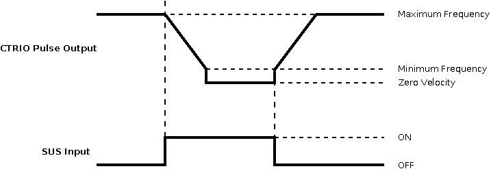
The third input (SUS) is the Suspend input. This input has different effects on the CTRIO output depending on the pulse profile specified by the Position File Number parameter:
Abrupt Suspend

Deceleration Suspend
Status Display:
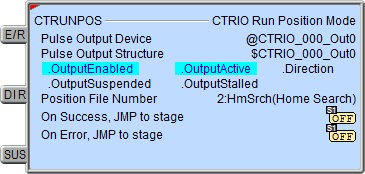
The Status display of the instruction
shows Values:
Target Position or Optional Target Position if a
CTRIO2 Trapezoid Plus or Trapezoid w / Limits profile is being used., and the Highlight:
.OutputEnabled,
.OutputActive,
.Direction,
.OutputSuspended,
.OutputStalled
bits.
CTRIO Structure Field Care-Abouts:
The following is a list of the"dot" fields of the CTRIO structure that are programmatically used with the CTRIO Run Position Mode (CTRUNPOS) instruction. To see a complete listing of all CTRIO structures and members, go to the Project Browser --> Configuration --> Memory --> I/O --> Specialty.
COLOR KEY
Blue: CTRIO Input
Maroon: CTRIO Output
Black: CTRIO Module
Silver: Not used for this instruction
Note: The red "x" is the digit 0, 1, 2, or 3.
NOTES:
(1)This structure member only available for CTRIO2 (not CTRIO). For CTRIO this remains zero.
See Also:
CTDYNPOS
- CTRIO Run Dynamic Position Mode
CTDYNVEL
- CTRIO Run Dynamic Velocity Mode
CTPLSADD
- CTRIO2 Add Entry to PLS
CTPLSEDT
- CTRIO2 Edit PLS Entry
CTREGWR -
CTRIO Write Register
CTRUNPOS - CTRIO Run Position Mode
CTRUNVEL
- CTRIO Run Velocity Mode
CTTBLADD
- CTRIO Add Entry to Preset Table
CTTBLEDT
- CTRIO Edit Preset Table Entry
Example 1 of 2:
Description of a Typical CTRIO Run Position Mode (CTRUNPOS) Stage Diagram:
This is a stage diagram of a simple sequence control that would home a motor to position and then allow any number of moves using the CTRUNPOS instruction, a CTRIO2 and a predefined Trapezoid PLUS Pulse Profile.

Initially the Home stage homes the motor. When this is complete it transitions to the Zero stage.
The Zero stage resets the CTRIO2 output position to zero (0) after the homing and then transitions to the Position stage.
The Position stage positions the motor depending upon a variable. When this position is reached it transitions to the InPos stage where the decision is made as to whether this was the last move or not.
The InPos stage is where the decision is made as to whether there is another position to move to, or if the sequence is complete. If it was not the last move, a new value is loaded in the position variable and transition is made back to the Position stage. If it was the last move then transition is made to the Stop stage.
The Stop stage simply exits the Program code block.
Description of a Typical CTRIO Run Position Mode (CTRUNPOS) Stage Ladder:
This is the ladder equivalent of the above stage diagram that uses the CTRUNPOS instruction which will home a stepper motor attached to the CTRIO2's pulse output and then allow any number of relative moves to subsequent positions and then stop.
Note: Since CTRIO2 pulse profiles are being used, this example cannot be used for a CTRIO module.
This example presupposes the existence of the following System Configuration for the CTRIO2 (PLC --> System Configuration --> Module Configuration(s) --> CTRIO_000 -->):
-
Configure I/O -->
-
Pulse Profiles -->
-
File 15 --> Trapezoid w/Limits -->
-
File 12 --> Trapezoid Plus -->
-
A stepper motor is wired to CTRIO2 Output 0 and Output 1.
-
A quadrature encoder associated with the stepper motor is wired to CTRIO2 Input A and Input B.
-
A normally open proximity sensor is wired to CTRIO2 Input D.

Home is the initial state which waits for HomeStart bit to come ON. The HomeDIR bit must be turned ON if home position is to be searched for in the counter-clockwise direction, or left OFF if home position is in the clockwise direction. This bit must be in the desired state before HomeStart bit is turned ON. The HomeSUS bit can be used to temporarily suspend the home-search. When the HomeStart bit comes ON, if there is an error the CTRUNPOS instruction will immediately transition to the ErrorHandler stage, where ladder logic should exist (not shown here) to handle the error (e.g. read $CTRIO_000.ErrorCode). If no error occurs the CTRUNPOS loads the Trapezoid w/Limits profile and begins to accelerate toward maximum frequency (according to the pulse profile's parameter values) searching for a signal on the CTRIO2's Input D. As configured in the profile, when the CTRIO2 sees the signal on Input D, the profile decelerates to the HomePosition value. When complete the CTRUNPOS transitions to the Zero stage.
Zero stage uses the CTREGWR instruction to write a zero (0) to the output position ($CTRIO_000_Out0.OutputPosition) and clears the quadrature encoder count by turning ON the $CTRIO_000_C1F1.Reset bit. If there is an error, transition is made to the ErrorHandler stage. If it completes without error, transition is made to the Position stage. When the Zero stage is exited, it will turn the $CTRIO_000_C1F1.Reset bit back OFF so the quadrature counter is free to count.
Position stage waits for PositionRun bit to come ON. Since the Position File Number being used is a Trapezoid Plus profile, the DIR input on the CTRUNPOS instruction has no effect (see chart above), thus, it is set to $Off. The PositionSUS bit can be used to temporarily suspend the move if necessary. Before the PositionRun bit is turned ON, the TargetPosition must be set to the desired relative position. If reverse motion is desired a negative number must be used. When the PositionRun bit comes ON, if there is an error the CTRUNPOS instruction will immediately transition to the ErrorHandler stage. If no error occurs the CTRUNPOS loads the Trapezoid Plus profile and begins to accelerate toward maximum frequency (according to the pulse profile's parameter values) and decelerate to the TargetPosition value position until it is reached. When the position is reached the CTRUNPOS instruction transitions to the InPos stage.
In the InPos stage the decision is made as to whether this was the last move or not. If there are more relative moves to be executed, a new relative position value must be written to TargetPosition and then the NextMove bit must be turned ON. Turning the NextMove bit ON, will turn itself OFF (to prevent multiple moves) and transition back to the Position stage for another execution of the CTRUNPOS instruction. If this was the last move, the Done bit is turned ON and the Program code block is exited.
Example 2 of 2: