DMD0534

CTTBLLD - CTRIO Load Table
The CTRIO Load Table (CTTBLLD) instruction is used to load one of the preconfigured Output Preset Tables in a CTRIO module, or one of the preconfigured PLS Tables in a CTRIO2 module, for one of the CTRIO's Discrete Outputs. The CTTBLLD instruction can be used with both the CTRIO and CTRIO2 module.
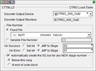
Parameters:
Note: Use the F9 key or click the 'three dot box' at the right edge of the parameter field to open the Default Element Selection Tool (the Element Picker or the Element Browser) or use the Down-Arrow key (Auto-Complete) on any parameter field to see a complete list of the memory locations that are valid for that parameter of the instruction.
Discrete Output Device - selects which preconfigured CTRIO Discrete Output device to use. Before this instruction can select a Discrete Output device, a CTRIO Device must be configured with at least one of its output channels setup for Discrete output mode.
no devices available - indicates that there are no CTRIO Discrete Output devices that have been configured that can perform this instruction.
create module - will open the Create New Module Configuration dialog where a CTRIO Module can be created and then a CTRIO Discrete Output device can then be configured.
Discrete Output Structure - This field displays the name of the Discrete Output structure that will be used by this instruction. This structure was created when the CTRIO module configuration was read during the Module Configuration phase.
File Number - specifies which of the preconfigured Output Preset Tables to load.
-
Fixed File - displays a list of the preconfigured Output Preset Tables and PLS Tables that were read from the CTRIO module during the Module Configuration phase. Select the desired file number from the list.
-
Variable File Number - specifies a memory location where the Output Preset table number resides. This can be any readable numeric location.
The On Success and On Error parameters specify what action to perform when this instruction completes. You do not have to use the same type of selection for both On Success and On Error.
If the Set Bit selection is used for either On Success or On Error, the specified BIT location will be SET OFF when the instruction is first enabled and will remain OFF until the instruction completes. Once complete, the appropriate Success or Error bit location ON. The specified Bit location is enabled with a SET (Latch) operation meaning that it will remain ON even if the input logic for the instruction goes OFF.
If the JMP to Stage selection is used for either On Success or On Error the target Stage must be in the same Program code-block as this instruction, you cannot specify a target Stage that exists in a different Program code-block. When the operation finishes, the target Stage will be enabled the same way as a standalone Jump to Stage (JMP) instruction would do it. The JMP to Stage option will only be available if this instruction is placed in a Program code-block.
On Success selects which of the following actions to perform if the operation is successful:
- Enable SET Bit then specify any writable bit location.
- Enable JMP to Stage then specify any
Stage number from S0 to S127 in the current Program code-block.
On Error selects which of
the following actions to perform if the operation is unsuccessful:
- Enable SET Bit then specify writable bit location.
- Enable JMP to Stage then specify any Stage number from S0 to S127 in the current Program code-block.
If either the On Success or On Error selections are set to JMP to Stage, Automatically create the SG box for any NEW stage number will be enabled which will automatically create any target stage that does not already exist.
- Below this rung will create the new target stage on a new rung following this instruction.
- At end of code-block will create the new target stage as the last rung of this Program.
Note: any time the On Error condition occurs, the CTRIO generates an Error Code that can be read in the <Module Name>.ErrorCode (Module Name is the name assigned
to the CTRIO in the Module Configuration). The List of Error Code values (in decimal) follows:
Status Display:
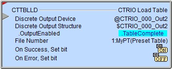
The Status display of the instruction shows the Values:
File Number, the Highlight:
.OutputEnabled,
and .TableComplete bits.
The red triangle in the upper left corner of the status display indicates this is a Fully Asynchronous instruction.
The gray triangle at the right end of the input leg indicates the input is edge-triggered, meaning this instruction will execute each time the input logic transitions from OFF to ON.
CTRIO Structure Field Care-Abouts:
The following is a list of the"dot" fields of the CTRIO structure that are programmatically used with the CTRIO Load Table (CTTBLLD) instruction. To see a complete listing of all CTRIO structures and members, go to the Project Browser --> Configuration --> Memory --> I/O --> Specialty.
COLOR KEY
Blue: CTRIO Input
Maroon: CTRIO Output
Black: CTRIO Module
Silver: Not used for this instruction
Note: The red "x" is the digit 0, 1, 2, or 3.
NOTES:
(1)This structure member only available for CTRIO2 (not CTRIO). For CTRIO this remains zero.
See Also:
CTDYNPOS - CTRIO Run Dynamic Position Mode
CTDYNVEL - CTRIO Run Dynamic Velocity Mode
CTPLSADD - CTRIO2 Add Entry to PLS
CTPLSEDT - CTRIO2 Edit PLS Entry
CTREGWR - CTRIO Write Register
CTRUNPOS - CTRIO Run Position Mode
CTRUNVEL - CTRIO Run Velocity Mode
CTTBLADD - CTRIO Add Entry to Preset Table
CTTBLEDT - CTRIO Edit Preset Table Entry
CTTBLLD - CTRIO Load Table
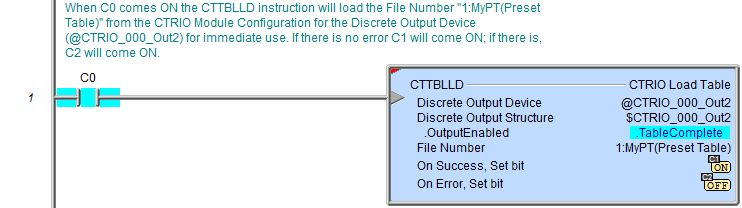
Example 1 of 2:
Description of a Typical CTRIO Load Table (CTTBLLD) Stage Diagram:
This is a stage diagram of a simple sequence control that loads a Preset Table for a CTRIO discrete output, enables the output and utilizes the Preset Table. When the table is complete, the discrete output is then disabled and the Preset table cleared out for this CTRIO discrete output.
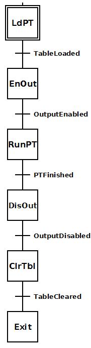
LdPT (Load Preset Table) is the initial stage that loads a particular Preset Table for a CTRIO discrete output. When loaded successfully it transitions to the next stage.
EnOut (Enable Output) stage resets a CTRIO input count (mechanically associated with the CTRIO pulse output) to zero and enables the CTRIO discrete output for use with the Preset Table just loaded. When successful it transitions to the next stage.
RunPT (Run Preset Table) runs a CTRIO pulse output that is associated with the CTRIO input count in order to make use of the Preset Table. When a certain number of pulses has been reached the process is complete and transition is made to the next stage to clean up.
DisOut (Disable Output) stage disables the CTRIO discrete output and transitions to the next stage.
ClrTbl (Clear Table) stage uses the CTTBLCLR instruction to clear the Preset Table from the CTRIO discrete output.
Exit stage exits the Program code block.
Description of a Typical CTRIO Clear Table (CTTBLLD) Stage Ladder:
To the right is equivalent ladder for the above stage diagram of a simple sequence control that loads a Preset Table for a CTRIO discrete output, enables the output and utilizes the Preset Table. When the table is complete, the discrete output is then disabled and the Preset table cleared out for this CTRIO discrete output.
This example presupposes the existence of the following System Configuration for the CTRIO (PLC --> System Configuration --> Module Configuration(s) --> CTRIO_000 -->):
-
Configure I/O -->
-
Discrete Tables --> Add Preset Table: with the following parameters:
File Number: 1
Name: MyPT
Scales: Unscaled
Entry: SET at 2000
Entry: RESET at 4000 -
A quadrature encoder is wired to CTRIO's Channel 1 Input A & B that is physically associated with the motor attached to the CTRIO's Output 0 & 1.
-
A stepper motor is wired to CTRIO's Output 0 & 1 that is physically associated with the quadrature encoder attached to the CTRIO's Channe 1 Input A & B.
-
A discrete device that utilizes the CTRIO's Output is wired to CTRIO's Output 2.
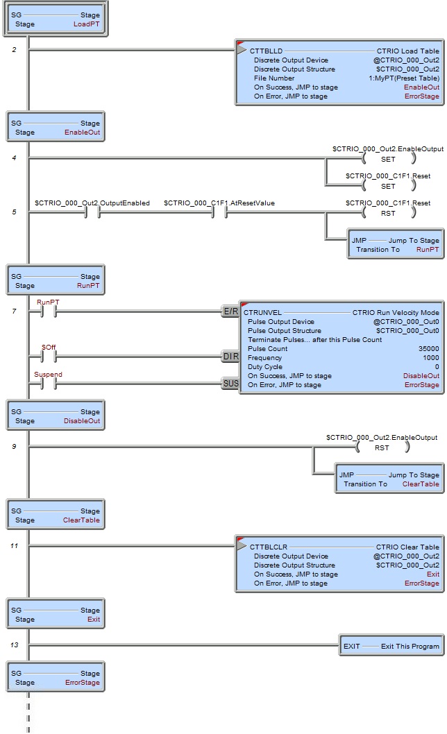
LoadPT (Load Preset Table) is the initial stage that executes a CTTBLLD instruction to load the MyPT Preset Table for CTRIO discrete output Out2. When loaded successfully it transitions to the EnableOut stage. If there is an error transition is made to the ErrorStage stage where logic (not shown here) should exist to handle the error.
EnableOut stage resets CTRIO Channel 1 Function 1 input count to zero and enables the CTRIO discrete output Out2 for use with the MyPT Preset Table just loaded. When the feedback bits (.OutputEnabled, .AtResetValue) show this is successful transition is made to the RunPT stage.
RunPT (Run Preset Table) executes a CTRUNVEL instruction that generates 35,000 pulses out the CTRIO pulse output Out0 at Frequency 1000 pps. If there is an error, transition is made to the ErrorStage stage. Since this output is physically associated with the CTRIO Channel 1 Function 1 quadrature encoder input, the input count increases, exercising the Preset Table and the CTRIO discrete output Out2. When 35,000 pulses have been output, the process is complete and transition is made to the DisableOut stage to clean up. Suspend bit is used to temporarily suspend the CTRUNVEL if need be.
DisableOut stage disables the CTRIO discrete output and transitions to the ClearTable stage.
ClearTable stage uses the CTTBLCLR instruction to clear the Preset Table from the CTRIO discrete output Out2 and transitions to the Exit stage. If there is an error, transition is made to the ErrorStage stage.
Exit stage exits the Program code block.
ErrorStage is where logic (not shown here) should exist to handle the errors for this sequence.
Example 2 of 2: