DMD0530

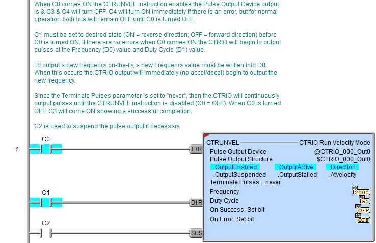
CTRUNVEL - CTRIO Run Velocity Mode
The CTRIO Run Velocity Mode (CTRUNVEL) instruction is used to run a Velocity Profile for the CTRIO module. The CTRUNVEL instruction can be used with both the CTRIO and CTRIO2 module.

Parameters:
Note: Use the F9 key or click the 'three dot box' at the right edge of the parameter field to open the Default Element Selection Tool (the Element Picker or the Element Browser) or use the Down-Arrow key (Auto-Complete) on any parameter field to see a complete list of the memory locations that are valid for that parameter of the instruction.
Pulse Output Device - selects which preconfigured CTRIO Pulse Output device to use. Before this instruction can select a Pulse Output device, a CTRIO Device must be configured with at least one of its output channels setup for Pulse / Direction or CW / CCW pulse output mode.
no devices available - indicates that there are no CTRIO Pulse Output devices that have been configured that can perform this instruction.
create module - will open the Create New Module Configuration dialog where a CTRIO Module can be created and then a CTRIO Pulse Output device can then be configured.
Pulse Output Structure - this field displays the name of the Pulse Output Structure that will be used by this instruction. This structure was created when the CTRIO module was configured during the Module Configuration phase.
Terminate Pulses - specifies the event that will cause the CTRIO to stop sending pulses. The terminating event can be specified in one of the following four ways:
never - pulses will be generated as long as the Enable / Reset input logic is ON.
after this Pulse Count - pulses will be generated until this pulse count is reached.
Pulse Count - specifies the total number of pulses to generate. This can be any positive integer value from 0 to 2147483647, or any readable numeric location.
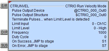
when Limit Level is detected - generate pulses at the described frequency until the following predefined Limit in the CTRIO is reached:
Limit Input - selects which of the following predefined Limit inputs to use.
0 - Ch1/C
1 - Ch1/D
2 - Ch2/C
3 - Ch2/D
Limit Level - selects which level of the predefined Limit to use:
0 - High
1 - Low
when Position is reached - generate pulses at the described frequency until the count value in the selected CTRIO input reaches a position value. Choose one of the 'greater than' selections if the value of the CTRIO Input is increasing toward the Position value; choose a 'less than' selection if the value of the CTRIO Input is decreasing toward the Position value.
Stop when - selects which of the predefined CTRIO Input values to use and the comparison operator:
- 0x00 - Ch1/Fn1 is less than
- 0x10 - Ch1/Fn1 is greater than
- 0x01 - Ch1/Fn2 is less than
- 0x11 - Ch1/Fn2 is greater than
- 0x02 - Ch2/Fn1 is less than
- 0x12 - Ch2/Fn1 is greater than
- 0x03 - Ch2/Fn2 is less than
- 0x13 - Ch2/Fn2 is greater than
Target Position - specifies the Position value to compare to the selected CTRIO Input value. This can be any integer value or any readable numeric location.
Frequency - specifies the frequency of the pulses generated. This can be any constant value from 0 to 25,000 for the CTRIO, or from 0 to 250,000 for the CTRIO2, or any readable numeric location. The minimum output frequency is 20Hz, so any Frequency value between 0 and 20 will result in a 20Hz output signal.
Duty Cycle - specifies the duty cycle of the pulses. A value of 0 is interpreted as 50%. This can be any constant value from 1 to 99 (corresponding directly to the duty cycle percentage), or any readable numeric location.
The On Success and On Error parameters specify what action to perform when this instruction completes. You do not have to use the same type of selection for both On Success and On Error.
If the Set Bit selection is used for either On Success or On Error, the specified BIT location will be SET OFF when the instruction is first enabled and will remain OFF until the instruction completes. Once complete, the appropriate Success or Error bit location ON. The specified Bit location is enabled with a SET (Latch) operation meaning that it will remain ON even if the input logic for the instruction goes OFF.
If the JMP to Stage selection is used for either On Success or On Error the target Stage must be in the same Program code-block as this instruction, you cannot specify a target Stage that exists in a different Program code-block. When the operation finishes, the target Stage will be enabled the same way as a standalone Jump to Stage (JMP) instruction would do it. The JMP to Stage option will only be available if this instruction is placed in a Program code-block.
On Success selects which of the following actions to perform if the operation is successful:
- Enable SET Bit then specify any writable bit location.
- Enable JMP to Stage then specify any
Stage number from S0 to S127 in the current Program code-block.
On Error selects which of
the following actions to perform if the operation is unsuccessful:
- Enable SET Bit then specify writable bit location.
- Enable JMP to Stage then specify any Stage number from S0 to S127 in the current Program code-block.
If either the On Success or On Error selections are set to JMP to Stage, Automatically create the SG box for any NEW stage number will be enabled which will automatically create any target stage that does not already exist.
- Below this rung will create the new target stage on a new rung following this instruction.
- At end of code-block will create the new target stage as the last rung of this Program.
Note: any time the On Error condition occurs, the CTRIO generates an Error Code that can be read in the <Module Name>.ErrorCode (Module Name is the name assigned to the CTRIO in the Module Configuration). The List of Error Code values (in decimal) follows:
Instruction Inputs:
The first input (E/R) in the Enable / Reset input. When this input logic is ON the specified Velocity Profile will be configured, and the Output will be enabled.
The second input (DIR) is the Direction. If the Direction input logic is OFF when the E/R input comes ON, the CTRIO will generate pulses for a move in the clockwise (positive) direction; If the Direction input logic is ON when the E/R input comes ON, the CTRIO will generate pulse for a move in the counter-clockwise (negative) direction.

The third input (SUS) is the Suspend input. When this input logic is ON the CTRIO will stop emitting output pulses. When this input logic goes back OFF the CTRIO will start emitting the remaining output pulses.
Status Display:

The Status display of this instruction shows Values: Frequency, Duty Cycle, Pulse Count, andTarget Position, and shows Highlight: .OutputEnabled, .OutputActive, .Direction, .OutputSuspended, and .OutputStalled. bits.
The red triangle in the upper left corner of the status display indicates this is a Fully Asynchronous instruction.
CTRIO Structure Field Care-Abouts:
The following is a list of the"dot" fields of the CTRIO structure that are programmatically used with the CTRIO Run Velocity Mode (CTRUNVEL) instruction. To see a complete listing of all CTRIO structures and members, go to the Project Browser --> Configuration --> Memory --> I/O --> Specialty.
COLOR KEY
Blue: CTRIO Input
Maroon: CTRIO Output
Black: CTRIO Module
Silver: Not used for this instruction
Note: The red "x" is the digit 0, 1, 2, or 3.
NOTES:
(1)This structure member only available for CTRIO2 (not CTRIO). For CTRIO this remains zero.
See Also:
CTDYNPOS
- CTRIO Run Dynamic Position Mode
CTDYNVEL
- CTRIO Run Dynamic Velocity Mode
CTPLSADD
- CTRIO2 Add Entry to PLS
CTPLSEDT
- CTRIO2 Edit PLS Entry
CTREGWR -
CTRIO Write Register
CTRUNPOS
- CTRIO Run Position Mode
CTRUNVEL - CTRIO Run Velocity
Mode
CTTBLADD
- CTRIO Add Entry to Preset Table
CTTBLEDT
- CTRIO Edit Preset Table Entry
Example 1 of 2:
Description of a Typical CTRIO Run Velocity Mode (CTRUNVEL) Stage Diagram:
This is a stage diagram of a simple sequence control that would home a motor to position and then allow any number of velocities using the CTRUNVEL instruction, a CTRIO and no predefined Pulse Profiles.
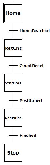
Initially the Home stage homes the motor to a proximity switch connected to the CTRIO input. When this is complete it transitions to the RstCnt (ResetCount) stage.
The RstCnt stage resets the CTRIO encoder input count to zero (0) since the starting position of the motor will be ascertained via encoder and then transitions to the StartPos (StartPosition) stage.
The StartPos stage positions the motor depending upon a variable and monitoring of the encoder input count of the CTRIO. When this position is reached it transitions to the GenPulse (GeneratePulses) stage where all subsequent velocities are executed. When all velocities have been completed, the transition is made to the Stop stage.
The Stop stage simply exits the Program code block
Description of a Typical CTRIO Run Velocity Mode (CTRUNVEL) Stage Ladder:
To the right is the ladder equivalent of the above stage diagram that uses the CTRUNVEL instruction which will home a motor to position and then allow any number of velocities using the CTRUNVEL instruction, a CTRIO and no predefined Pulse Profiles.
This example presupposes the existence of the following System Configuration for the CTRIO (PLC --> System Configuration --> Module Configuration(s) --> CTRIO_000 -->):
-
Configure I/O -->
-
A stepper motor is wired to CTRIO Output 0 and Output 1.
-
A quadrature encoder associated with the stepper motor is wired to CTRIO2 Input A and Input B.
-
A normally open proximity sensor is wired to CTRIO Input D.
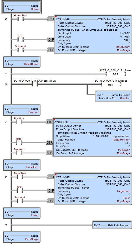
Home is the initial state which waits for HomeStart bit to come ON. The direction (DIR input leg) is assumed to be in the reverse direction thus it is always ON ($On). The Suspend bit can be used to temporarily suspend the home-search. When the HomeStart bit comes ON, if there is an error the CTRUNVEL instruction will immediately transition to the ErrorStage stage, where ladder logic should exist (not shown here) to handle the error (e.g. read $CTRIO_000.ErrorCode). If no error occurs the CTRUNVEL enables the output and begins generating pulses at the Frequency (1000) value looking for a high level on Ch1D input. When the CTRIO sees the signal on Input D, pulses are stopped and transition is made to the ResetCount stage.
Since the starting position of the motor will be ascertained via encoder, the ResetCount stage resets the input count by turning the $CTRIO_000_C1F1.Reset bit ON. When the CTRIO acknowledges this reset has occurred, $CTRIO_000_C1F1.AtResetValue bit will come ON. When this feedback bit comes ON it will turn the $CTRIO_000_C1F1.Reset bit OFF (so channel 1 can count) and transitions to the Position stage.
Position stage waits for Position bit to come ON. The direction (DIR input leg) is assumed to be in the forward direction thus it is always OFF ($Off). The Suspend bit can be used to temporarily suspend the positioning. Before the Position bit is turned ON, the TargetPosition must be set to the desired position. When the Position bit comes ON, if there is an error the CTRUNVEL instruction will immediately transition to the ErrorStage stage. If no error occurs the CTRUNVEL generates pulses at the Frequency value (500) until the Stop When parameter conditions are met. When the position is reached the CTRUNVEL instruction transitions to the PulseGen stage.
The PulseGen stage waits for the PulseStart bit to come ON. The direction (DIR input leg) is assumed to be in the forward direction thus it is always OFF ($Off). The Suspend bit can be used to temporarily suspend the pulse generation. Before the PulseStart bit is turned ON, the TargetFreq must be set to the desired frequency. When the PulseStart bit comes ON, if there is an error the CTRUNVEL instruction will immediately transition to the ErrorStage stage. If no error occurs the CTRUNVEL generates pulses at the Frequency value (500) "forever" (because the Terminate Pulses parameter is set to "never"). While the CTRUNVEL instruction is running any number of different frequency values can be written to the Frequency parameter, TargetFreq, and the CTRIO output will immediately (i.e. no acceleration/deceleration) generate pulses at that frequency. When all desired frequencies have been completed the PulseStart bit must be turned OFF. This will cause the CTRIO output to stop generating pulses immediately and transition to the Finish stage.
The Finish stage simply exits this Program code block.
Example 2 of 2: