Topic: DMD0522

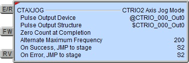
CTAXJOG - CTRIO2 Axis Jog Mode
This instruction can only be used with the CTRIO2 module.
The CTRIO2 Axis Jog Mode (CTAXJOG) instruction is used to put the Pulse Output Device into the Jog Mode which allows for manually moving the Pulse Output in forward and reverse directions. Once in Jog Mode, moves are commanded by turning ON either the FW (Forward) or RV (Reverse) input leg. CTAXJOG can optionally move with a slower speed (Alternate Maximum Frequency) than was configured for the axis by the CTAXCFG instruction, otherwise the moves will execute using the parameters defined by a previously executed Axis Configuration (CTAXCFG) instruction.

Parameters:
Note: Use the F9 key or click the 'three dot box' at the right edge of the parameter field to open the Default Element Selection Tool (the Element Picker or the Element Browser) or use the Down-Arrow key (Auto-Complete) on any parameter field to see a complete list of the memory locations that are valid for that parameter of the instruction.
Pulse Output Device - selects which preconfigured CTRIO Pulse Output device to use. Before this instruction can select a Pulse Output device, a CTRIO Device must be configured with at least one of its output channels setup for Pulse / Direction or CW / CCW pulse output mode.
no devices available - indicates that there are no CTRIO Pulse Output devices that have been configured that can perform this instruction.
create module - will open the Create New Module Configuration dialog where a CTRIO Module can be created and then a CTRIO Pulse Output device can then be configured.
Pulse Output Structure - this field displays the name of the Pulse Output Structure that will be used by this instruction. This structure was created when the CTRIO module was configured during the Module Configuration phase.
Zero Count at Completion- optionally elect to reset the current position value for the Pulse Output (.OutputPosition = 0) once the E/R input logic is OFF signifying the completion of the CTRIO2 Axis Jog Mode (CTAXJOG).
Alternate Maximum Frequency- optionally designates the frequency (in pulses per second) that the pulse output will ramp towards that is different from what is specified in the Axis Configuration (CTAXCFG) instruction. This can be any positive constant value or any readable numeric location.
The On Success and On Error parameters specify what action to perform when this instruction completes. You do not have to use the same type of selection for both On Success and On Error.
If the Set Bit selection is used for either On Success or On Error, the specified BIT location will be SET OFF when the instruction is first enabled and will remain OFF until the instruction completes. Once complete, the appropriate Success or Error bit location ON. The specified Bit location is enabled with a SET (Latch) operation meaning that it will remain ON even if the input logic for the instruction goes OFF.
If the JMP to Stage selection is used for either On Success or On Error the target Stage must be in the same Program code-block as this instruction, you cannot specify a target Stage that exists in a different Program code-block. When the operation finishes, the target Stage will be enabled the same way as a standalone Jump to Stage (JMP) instruction would do it. The JMP to Stage option will only be available if this instruction is placed in a Program code-block.
On Success selects which of the following actions to perform if the operation is successful:
- Enable SET Bit then specify any writable bit location.
- Enable JMP to Stage then specify any
Stage number from S0 to S127 in the current Program code-block.
On Error selects which of
the following actions to perform if the operation is unsuccessful:
- Enable SET Bit then specify writable bit location.
- Enable JMP to Stage then specify any Stage number from S0 to S127 in the current Program code-block.
If either the On Success or On Error selections are set to JMP to Stage, Automatically create the SG box for any NEW stage number will be enabled which will automatically create any target stage that does not already exist.
- Below this rung will create the new target stage on a new rung following this instruction.
- At end of code-block will create the new target stage as the last rung of this Program.
Note: any time the On Error condition occurs, the CTRIO generates an Error Code that can be read in the <Module Name>.ErrorCode (Module Name is the name assigned to the CTRIO in the Module Configuration). The List of Error Code values (in decimal) follows:
Instruction Inputs:
The first input (E/R) in the Enable / Reset input. When this input logic is ON the specified Pulse Output will be enabled (.OutputEnabled = ON) and as long as both the FW input logic and the RV input logic are OFF then the specified Pulse Output will also be suspended (.OutputSuspended = ON).
The second input (FW) is the Forward input. When the E/R input is ON and this input logic is ON the CTRIO2 will emit pulses for the forward (clockwise) direction, ramping up to the Maximum Frequency using the Acceleration Rate specified in the Axis Configuration (CTAXCFG) instruction - if an optional Alternate Maximum Frequency is specified the ramp will use this value instead. When FW goes OFF the CTRIO2 will ramp down to zero using the Deceleration Rate specified in the Axis Configuration (CTAXCFG) instruction.
The third input (RV) is the Reverse input. When the E/R input is ON and this input logic is ON the CTRIO2 will emit pulses for the reverse (counter-clockwise) direction, ramping up to the Maximum Frequency using the Acceleration Rate specified in the Axis Configuration (CTAXCFG) instruction - if an optional Alternate Maximum Frequency is specified the ramp will use this value instead. When RV goes OFF the CTRIO2 will ramp down to zero using the Deceleration Rate specified in the Axis Configuration (CTAXCFG) instruction.
Note: if both the Forward (FW) and Reverse (RV) inputs are ever on at the same time the CTRIO2's output will be suspended and will decelerate to zero (0) at the Deceleration Rate specified in the Axis Configuration (CTAXCFG).

Status Display:
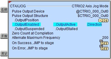
The status display of the instruction shows Values: .OutputPosition, Zero Count at Completion (if configured), and Alternate Maximum Frequency (if configured), and Highlight: .OutputEnabled, .OutputActive, .Direction, .OutputSuspended, .OutputStalled bits.
The red triangle in the upper left corner of the status display indicates this is a Fully Asynchronous instruction.
CTRIO2 Structure Field Care-Abouts:
The following is a list of the"dot" fields of each Pulse Output Structure that are programmatically used with the CTRIO2 Axis Jog Mode (CTAXJOG) instruction. To see a complete listing of all CTRIO structures and members, go to the Project Browser --> Configuration --> Memory --> I/O --> Specialty.
COLOR KEY
Blue: CTRIO2 Input
Maroon: CTRIO2 Output
Black: CTRIO2 Module
Silver: Not used for this instruction
Note: The red "x" is the digit 0, 1, 2, or 3.
NOTES:
(1)This structure member only available for CTRIO2 (not CTRIO). For CTRIO this remains zero.
See Also:
CTRIO2 Axis Run Dynamic Position Mode
CTRIO2 Axis Run Dynamic Velocity Mode
CTRIO2 Axis Run Trapezoid w/ Limits
CTRIO2 Axis Jog Mode
Example 1 of 2:
Description of a Typical CTRIO2 Axis Jog Mode (CTAXJOG) Stage Diagram:
This is a stage diagram of a simple sequence control that would use a stepper motor to manually home a machine.
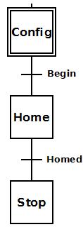
Initially the Config stage waits for Begin to come ON. When Begin comes ON, the CTRIO2 axis is defined and the process transitions to the Home stage.
The Home stage remains enabled until the operator has manually positioned the machine to his satisfaction, then manually sets the Homed button.
The Stop stage simply exits the Program code block.
Description of a Typical CTRIO2 Axis Jog Mode (CTAXJOG) Stage Ladder:
This is the ladder equivalent of the above stage diagram that uses the CTAXJOG instruction to manually home a machine.
This example presupposes the existence of the following System Configuration for the CTRIO2 (PLC --> System Configuration --> Module Configuration(s) --> CTRIO_000 -->):
-
Configure I/O --> Outputs --> Out0 --> Pulse (Step/Dir) or Pulse (CW/CCW).
-
A stepper motor is wired to CTRIO2's Output 0 and Output 1.
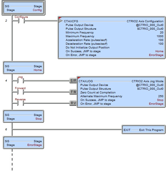
Config is the initial stage and waits for the input Configure bit to come ON. When it does the CTRIO2 axis is configured using the CTAXCFG instruction. If there is an error then transition is made to the ErrorStage stage where ladder logic should exist (not shown here) that would properly handle the error (e.g. to process the $CTRIO_000.ErrorCode value). If the configuration was successful, then transition is made to the Home stage. Since the CTAXCFG is configured to Do Not Initialize Output Position then $CTRIO_000_Out0.OutputPosition is not zeroed.
Home is the main CTAXJOG instruction stage. This stage must be remain enabled during the entire jogging process. When the Jog bit is turned ON the following happens:
-
If there is an error then the transition is immediately made to the ErrorStage stage.
-
If there is no error, then the CTRIO2's Pulse Output is enabled ($CTRIO_000_Out0.OutputEnabled = ON).
-
The CTRIO2's Pulse Output is suspended ($CTRIO_000_Out0.OutputSuspended = ON).
-
The CTRIO2 Pulse Output Device is temporarily reconfigured to use a Maximum Frequency of 250 instead of the 1000 that was initially set by the CTAXCFG instruction.
The Jog bit will remain ON until the jogging process is complete. When the Jog bit is reset to OFF the CTAXJOG instruction terminates and transitions to the Stop stage.
The Forward and Reverse bits are used to move the motor clockwise and counter-clockwise respectively. When either one of these bits is set the $CTRIO_000_Out0.OutputSuspended bit will go OFF and the motor will accelerate to the Alternate Maximum Frequency value. When that bit goes OFF, the motor will decelerate back to zero and the $CTRIO_000_Out0.OutputSuspended bit will come back ON.
Once the CTAXJOG is disabled the following happens:
-
The CTRIO2 Pulse Output is disabled ($CTRIO_000_Out0.OutputEnabled = OFF).
-
Because of the CTAXJOG parameter "Zero Count at Completion", the CTRIO Output Position is zeroed ($CTRIO_000_Out0.OutputPosition = 0).
-
The CTRIO's Pulse Output is no longer suspended ($CTRIO_000_Out0.OutputSuspended = OFF).
-
The On Success transitions to the Stop stage.
The Stop stage merely exits this Program code block.
Example 2 of 2:
