Topic: DMD0519

CTAXDYNP - CTRIO2 Axis Run Dynamic Position Mode
This instruction can only be used with the CTRIO2 module.
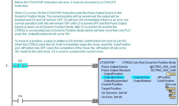
The CTRIO2 Axis Run Dynamic Position Mode (CTAXDYNP) instruction is used to put the Pulse Output Device into Dynamic Position Mode, allowing successive moves to be easily commanded. Once in Dynamic Position Mode, moves are commanded by changing the Target Position value and setting (one-shot) the .GotoPosition bit for the Pulse Output Device. The moves will execute using the parameters defined by a previously executed Axis Configuration (CTAXCFG) instruction.
Parameters:
Note: Use the F9 key or click the 'three dot box' at the right edge of the parameter field to open the Default Element Selection Tool (the Element Picker or the Element Browser) or use the Down-Arrow key (Auto-Complete) on any parameter field to see a complete list of the memory locations that are valid for that parameter of the instruction.
Pulse Output Device - selects which preconfigured CTRIO Pulse Output device to use. Before this instruction can select a Pulse Output device, a CTRIO Device must be configured with at least one of its output channels setup for Pulse / Direction or CW / CCW pulse output mode.
no devices available - indicates that there are no CTRIO Pulse Output devices that have been configured that can perform this instruction.
create module - will open the Create New Module Configuration dialog where a CTRIO Module can be created and then a CTRIO Pulse Output device can then be configured.
Pulse Output Structure - this field displays the name of the Pulse Output Structure that will be used by this instruction. This structure was created when the CTRIO module was configured during the Module Configuration phase.
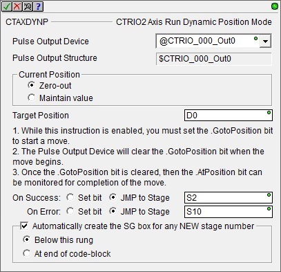
Current Position - this option specifies what action to take regarding the current position value when the instruction is enabled:
-
Zero-out- initialize the current position value for the Pulse Output to 0, .OutputPosition will be set to 0.
-
Maintain value - leaves the current position value for the Pulse Output intact, .OutputPosition will remain at whatever value it has.
Target Position - specifies the pulse count of the target position. The direction (clockwise or counter-clockwise) is inferred from the difference between the Target Position and the current position (.OutputPosition), that is, if the Target Position is greater than the current position, pulses for a clockwise move are emitted; if the Target Position is less than the current position, pulses for a counter-clockwise move are emitted. This can be any positive or negative constant value or any readable numeric location.
The On Success and On Error parameters specify what action to perform when this instruction completes. You do not have to use the same type of selection for both On Success and On Error.
If the Set Bit selection is used for either On Success or On Error, the specified BIT location will be SET OFF when the instruction is first enabled and will remain OFF until the instruction completes. Once complete, the appropriate Success or Error bit location ON. The specified Bit location is enabled with a SET (Latch) operation meaning that it will remain ON even if the input logic for the instruction goes OFF.
If the JMP to Stage selection is used for either On Success or On Error the target Stage must be in the same Program code-block as this instruction, you cannot specify a target Stage that exists in a different Program code-block. When the operation finishes, the target Stage will be enabled the same way as a standalone Jump to Stage (JMP) instruction would do it. The JMP to Stage option will only be available if this instruction is placed in a Program code-block.
On Success selects which of the following actions to perform if the operation is successful:
- Enable SET Bit then specify any writable bit location.
- Enable JMP to Stage then specify any
Stage number from S0 to S127 in the current Program code-block.
On Error selects which of
the following actions to perform if the operation is unsuccessful:
- Enable SET Bit then specify writable bit location.
- Enable JMP to Stage then specify any Stage number from S0 to S127 in the current Program code-block.
If either the On Success or On Error selections are set to JMP to Stage, Automatically create the SG box for any NEW stage number will be enabled which will automatically create any target stage that does not already exist.
- Below this rung will create the new target stage on a new rung following this instruction.
- At end of code-block will create the new target stage as the last rung of this Program.
Note: any time the On Error condition occurs, the CTRIO generates an Error Code that can be read in the <Module Name>.ErrorCode (Module Name is the name assigned to the CTRIO in the Module Configuration). The List of Error Code values (in decimal) follows:
Instruction Inputs:

The first input (E/R) is the Enable / Reset input. When this input logic comes ON the Pulse Output Device is placed in the "Dynamic Positioning Mode", the current position value will be set to 0 or maintained (i.e. .OutputPosition) and the Output will be enabled (.OutputEnabled = ON). It must remain ON until all desired positions have been reached. When this input logic goes OFF the Pulse Output Device is removed from "Dynamic Positioning Mode", the Output will be disabled (.OutputEnabled = OFF) and the On Success or On Error bits are set.
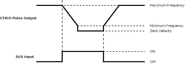
The second input (SUS) is the Suspend input.
When this input logic transitions ON, the
CTRIO2 will ramp down to zero using the Deceleration
Rate specified in the Axis Configuration (CTAXCFG). Click
here for more information on the Axis Configuration instruction. No
additional pulses will be emitted as long as this input remains ON.
When this input logic transitions OFF, the CTRIO2 will ramp up to the Maximum Frequency at Acceleration
Rate specified in the Axis Configuration (CTAXCFG) toward the Target Position. Click
here for more information on the Axis Configuration instruction.
Status Display:
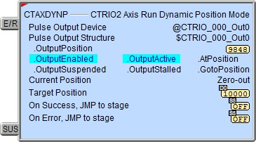
The status display of the instruction shows Values: .OutputPosition, Target Position, and Current Position, and Highlight: .OutputEnabled, .OutputActive, .AtPosition, .OutputSuspended, .OutputStalled, and .GotoPosition bits.
The red triangle in the upper left corner of the status display indicates this is a Fully Asynchronous instruction.
CTRIO2 Structure Field Care-Abouts:
The following is a list of the"dot" fields of the CTRIO2 structure that are programmatically used with the CTRIO2 Axis Run Dynamic Position Mode (CTAXDYNP) instruction. To see a complete listing of all CTRIO structures and members, go to the Project Browser --> Configuration --> Memory --> I/O --> Specialty.
COLOR KEY
Blue: CTRIO2 Input
Maroon: CTRIO2 Output
Black: CTRIO2 Module
Silver: Not used for this instruction
Note: The red "x" is the digit 0, 1, 2, or 3.
NOTES:
(1)This structure member only available for CTRIO2 (not CTRIO). For CTRIO this remains zero.
See Also:
CTRIO2 Axis Run Dynamic Position Mode
CTRIO2 Axis Run Dynamic Velocity Mode
CTRIO2 Axis Run Trapezoid w/ Limits
Example 1 of 2:
Description of a Typical CTRIO2 Axis Configuration (CTAXCFG) Stage Diagram:
This is a stage diagram of a simple sequence control that would move a motor to any number of positions and stop.

Initially the Config stage waits for Begin to come ON. When Begin comes ON, the CTRIO2 axis is configured and the process transitions to the Position stage.
The Position stage puts the CTRIO2 pulse output in the Dynamic Position mode. Once this is complete (Ready = ON) then the Move stage is enabled (not transitioned to). The reason for this is because the Position stage must remain enabled to keep the CTRIO2 pulse output in the Dynamic Position mode through the whole process.
The Move stage sets the CTRIO2's GotoPosition bit and waits for the AtPosition bit to come on indicating the pulse output has reached its position (Positioned = ON). Then the stage transitions to the InPos stage.
The InPos stage waits for either the NextMove or the Done buttons. If this was the last move, then the Done button converges both the Position and InPos stage and transitions to the Stop stage. If this was not the last move, then another position is given and the NextMove button transitions back to the Move stage.
The Stop stage simply exits this Program code block.
Description of a Typical CTRIO2 Axis Configuration (CTAXCFG) Stage Ladder:
This is the ladder equivalent of the above stage diagram that uses the CTAXDYNP instruction which will move a stepper motor attached to the CTRIO2's pulse output to any number of subsequent positions utilizing an axis configuration (CTAXCFG) profile, and then stop. Click here for more information on the CTAXCFG instruction.
This example presupposes the existence of the following System Configuration for the CTRIO2 (PLC --> System Configuration --> Module Configuration(s) --> CTRIO_000 -->):
-
Configure I/O --> Outputs --> Out0 --> Pulse (Step/Dir) or Pulse (CW/CCW).
-
A stepper motor is wired to CTRIO2's Output 0 and Output 1.
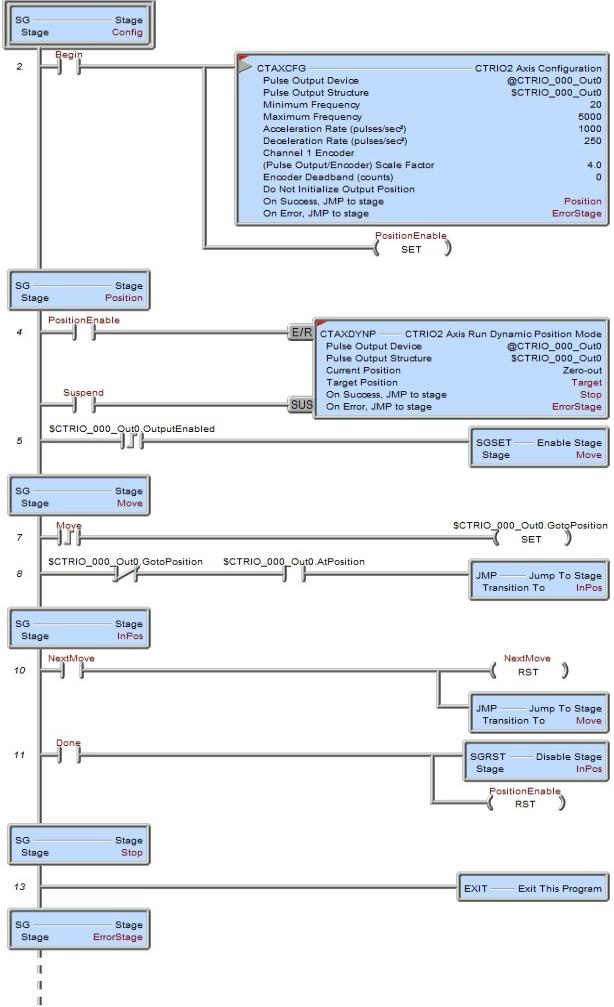
Config is the initial stage which waits for the input Begin to come ON. It is assumed that the first position value is loaded into the Target variable before turning on the Begin bit. Once Begin comes ON the PositionEnable bit is set ON, the CTAXCFG instruction configures an axis and when it is finished it jumps to the Position stage.
Position is the main CTAXDYNP instruction stage. This stage remains enabled during all moves. Instead of transitioning to the next stage (Move), the next stage will merely be enabled. PositionEnable is already ON when first entering this stage and will enable the CTAXDYNP instruction. Then the following things occur:
-
The Pulse Output Device ($CTRIO_000_Out0) will be placed in the "Dynamic Position Mode."
-
The current position value ($CTRIO_000_Out0.OutputPosition) is set to 0 because the Current Position parameter is set to "Zero-out".
-
The CTRIO2's Pulse Output is enabled ($CTRIO_000_Out0.OutputEnabled = ON).
The PositionEnable bit will remain ON for all moves. It will be cleared OFF at the completion of the last move.
The CTAXDYNP's SUS (Suspend) input is controlled by the Suspend bit. This bit must remain OFF for any given move to complete. Turning this bit ON will cause the CTRIO2's output to decelerate and stop. Turning it back OFF will cause the CTRIO2's output to accelerate and complete a move.
The On Success parameter jumps to the Stop stage. This will occur when PositionEnable is cleared OFF and everything was successful.
The On Error parameter jumps to the ErrorStage stage. In this stage should exist logic (not shown here) that would properly handle the error (e.g. to process the $CTRIO_000.ErrorCode value).
Once the CTAXDYNP is enabled, the $CTRIO_000_Out0.OutputEnabled bit will be set ON by the Pulse Output Device (this could take a couple of scans). When this occurs the next stage (Move) is enabled.
Move stage accomplishes all moves. In order to do this the newest position value is assumed to be already written to the Target and the $CTRIO_000_Out0.GotoPosition bit is set ON. The Pulse Output Device will clear this bit when the move begins. Once the bit is cleared, then the $CTRIO_000_Out0.AtPosition bit is monitored for completion of the move. Once that bit is set ON by the Pulse Output Device, this move is complete and the Move stage transitions to the InPos stage.
The InPos stage waits for either the NextMove or Done bit. If this was not the last move, then a new position value is written to the Target variable and the NextMove bit is toggled. This causes a transition back to the Move stage. If this was the last move, then the Done bit is toggled. This disables the InPos stage and resets the PositionEnable bit.
The PositionEnable bit resets the CTAXDYNP instruction in the Position stage above. This causes the following to happen:
-
The CTRIO2 pulse output is disabled ($CTRIO_000_Out0.OutputEnabled = OFF).
-
The On Success transitions to the Stop stage.
The Stop stage merely exits this Program code block.
Example 2 of 2: