Topic: DMD0553
![]()
CTRIO Input Scaling Wizard
To get to the CTRIO Input Scaling Wizard:
-
Follow this menu path: PLC --> System Configuration --> Module Configuration(s). This pulls up the System Configuration dialog.
-
Double-click on the CTRIO to configure. This pulls up the Edit CTRIO/CTRIO2 Configuration dialog.
-
Press the <Configure I/O> button. This pulls up the Configure IO dialog.
-
If a particular CTRIO input has been configured as a counter or quad counter, the in the upper right hand corner of the Function box is a button that looks like a ruler (see below). Press this button.
![]()
The Scaling Wizard is used to scale raw counts from one of the counter functions to engineering units, or to scale time values from one of the timer functions to engineering units. The options for scaling counter functions are different than those for scaling timer functions.

The following list shows what scaling types are available for which CTRIO input function:
-
Counter (Position, Rate)
As shown in the dialog itself, the scaling types are:
-
Position - Click here for help on Position
-
Rate - Click here for help on Rate
-
Interval - Click here for help on Interval
Once the scaling type is chosen, the <OK> button will change to a <Next> button. Pressing the <Next> button will then proceed to that scaling type's particular dialog.
Position Scaling
Position scaling converts raw counts to engineering units using linear interpolation. User provides minimum raw value, maximum raw value, minimum scaled value and maximum scaled value. It is typically used for units of distance, position, size, etc.
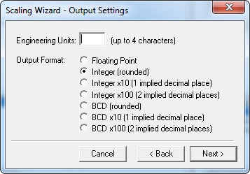
The first dialog to appear is the Output Settings. Options are:
-
Engineering Units - This is an optional 4-character alphanumeric used only for documentation purposes. Typical entries might be, for example, IN (for inches), FT (for feet), M (for meters), etc. Whatever text is entered here will be shown in the Edit CTRIO/CTRIO2 Configuration dialog under the particular CTRIO channel using the position scaling.
-
Output Format - This is the format of the engineering unit value that will be reported back to the CTRIO structure, storing the scaled value in the first register and moving the raw value (which is normally stored in the first register) to the second register:
Note: New applications should use the 'Floating Point' or 'Integer' options.
-
Floating Point, for example:
-
$CTRIO_000_C1F1.fReg1 - Channel 1 function 1, scaled floating-point value, register 1
-
$CTRIO_000_C1F1.iReg2 - Channel 1 function 1, raw signed integer value, register 2
-
Integer (rounded), Integer x10 (1 implied decimal place), Integer x100 (2 implied decimal places), BCD (rounded), BCD x 10 (1 implied decimal place) & BCD x 100 (2 implied decimal places), for example:
-
$CTRIO_000_C1F1.iReg1 - Channel 1 function 1, scaled value, register 1
-
$CTRIO_000_C1F1.iReg2 - Channel 1 function 1, raw value, register 2
Pressing the <Back> button goes back to the Scaling Wizard scaling type dialog above.
Pressing the <Next> button goes forward to allow entry of the scaling values.
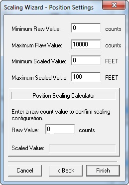
The position rate scaling values are entered here. Only 4 values are needed. The Minimum Raw Value will directly correspond to the Minimum Scaled Value. The Maximum Raw Value will directly correspond to the Maximum Scaled Value. Using the default values shown, therefore, if 10,000 pulses are seen on the CTRIO input, the .iReg1 (or .fReg1) CTRIO structure will contain the value of 100 in the format chosen.
The "Position Scaling Calculator" box has nothing to do with the scaling. Instead it is merely an embedded tool in this dialog window that allows the scaling values to be experimented with and checked. By typing in any number into Raw Value the Scaled Value text window will show the resultant scaled value.
Pressing the <Back> button goes back to the Output Settings dialog shown above.
Pressing the <Finish> button will exit back to the main Configure IO dialog.
Rate Scaling
Rate scaling converts raw counts to engineering units by sampling the count and normalizing to a desired time base. User provides counts per unit, scale offset, unit time base, calculation interval and data smoothing parameters. It is typically used for units of speed, flow, velocity, etc. Rate scaling is particularly preferred over interval scaling for count frequencies over 5 KHz, although it may be used for lower frequencies with increased sample times.
The first dialog to appear is the Output Settings. Options are:
-
Engineering Units - This is an optional 4-character alphanumeric used only for documentation purposes. Typical entries might be, for example, ips (for inches per second), fps (for feet per second), RPM (for revolutions per minute), etc. Whatever text is entered here will be shown in the Edit CTRIO/CTRIO2 Configuration dialog under the particular CTRIO channel using the rate scaling.
-
Output Format - This is the format of the engineering unit value that will be reported back to the CTRIO structure, storing the scaled value in the first register and moving the raw value (which is normally stored in the first register) to the second register:
Note: New applications should use the 'Floating Point' or 'Integer' options.
-
Floating Point, for example:
-
$CTRIO_000_C1F1.fReg1 - Channel 1 function 1, scaled floating-point value, register 1
-
$CTRIO_000_C1F1.iReg2 - Channel 1 function 1, raw signed integer value, register 2
-
Integer (rounded), Integer x10 (1 implied decimal place), Integer x100 (2 implied decimal places), BCD (rounded), BCD x 10 (1 implied decimal place) & BCD x 100 (2 implied decimal places), for example:
-
$CTRIO_000_C1F1.iReg1 - Channel 1 function 1, scaled value, register 1
-
$CTRIO_000_C1F1.iReg2 - Channel 1 function 1, raw value, register 2
Pressing the <Back> button goes back to the Scaling Wizard scaling type dialog above.
Pressing the <Next> button goes forward to allow entry of the scaling parameters.
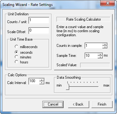
The rate scaling is done by setting 3 parameters in the Unit Definition box. A rate is a velocity. Thus the resultant value will be some distance unit (e.g. inches, feet, revolutions, etc.) per some time unit (milliseconds, seconds, minutes, hours). The parameters are:
-
Counts / unit - This is the number of counts per velocity unit
-
Scale Offset - This is the constant amount to adjust the result by. Most of the time this is zero (0).
-
Unit Time Base - This is the time base for the unit being measured.
The other two boxes (Calc Options & Rate Scaling Calculator) are not used in the formula and will be explained after the rate-scaling examples below.
The easiest way to learn what settings to use is by example.
Rate Scale Example #1
An RPM (revolutions per minute) value is needed for a motor whose encoder is wired to the CTRIO input. The encoder attached to the motor and providing pulses to the CTRIO input is an 800-ppr (pulses per revolution) encoder.
-
Since the desired unit is RPM (revolutions per minute) a Unit Time Base of minutes is selected.
-
The encoder yields 800 pulses in 1 revolution. Thus if it made 1 revolution in 1 minute, that would yield 800 pulses in 1 minute's time. So if the CTRIO input sees 800 pulses in the time span of 1 minute, that would be 1 RPM. Thus, Counts / unit is equal to 800 (meaning 800 pulses per minute = 1 RPM).
-
Scale Offset is zero because when there are no pulses being generated, that would be 0 RPM (i.e. nothing needs to be added to the result.)
If these values are selected for the Unit Definition box they can be double-checked by using the embedded tool Rate Scaling Calculator. For instance, to see the Scaled Value result, plug in the following values:
-
Counts in sample: 800 (in other words the 800-ppr encoder has revolved one time)
-
Sample Time: Since it is known if 800 pulses are received in 1 minute it would equal 1 RPM, then enter 60,000 (because 60 seconds in a minute, and the value is in milliseconds).
-
Notice the result will yield 1 RPM.
-
If a Sample Time was entered of 1000 ms (i.e. 1 second), this means the encoder is revolving 1 time per second. Thus it would revolve 60 times in a 60 seconds, thus the result is 60 RPM.
-
If a Sample Time was entered of 250 ms (i.e. 0.25 seconds), this means the encoder is revolving 4 times per second. The result would be 240 RPM.
Rate Scale Example #2
An fps (feet per second) value is needed for a conveyor belt. This conveyor belt is driven by a roller that is 10 inches in diameter. Attached to this roller is the same 800 ppr encoder. Thus:
-
Since the desired unit is fps (feet per second) a Unit Time Base of seconds is selected.
-
In order to figure out the Counts / unit the number of pulses received by the CTRIO when the conveyor belt moves 1 foot must be calculated. Since the roller is 10 inches in diameter and the belt is wrapped around it, the circumference must be calculated first. This is its diameter times pi.
10 inches x 3.14159 = 31.4159 inches
Thus when the roller rotates one full turn it has moved the conveyor 31.4159 inches. This 1 turn of the roller would also turn the encoder 1 full turn, and thus generate 800 pulses. Thus 800 pulses = 31.4159 inches of belt movement. Since the desired unit is feet per second and there are 12 inches per foot, then:
31.4159 inches / 12 in/ft = 2.618 feet.
This means when the roller turns 1 full turn, it has moved the belt 2.618 feet. Again, this 1 turn of the roller would also generate 800 pulses. Thus, 800 pulses = 2.618 feet of belt movement. So how many pulses will be seen if the belt only travels 1 foot?
800 pulses / 2.618 feet = 305.577 pulses per foot
Thus, Counts / unit is 305.577. Of course the CTRIO cannot see a fraction of a pulse, but a fraction can be used in the calculation. -
Scale Offset is zero, as usual.
If these values are selected for the Unit Definition box they can be double-checked by using the embedded tool Rate Scaling Calculator. For instance, to see the Scaled Value result, plug in the following values:
-
Counts in sample: 800 (in other words the 800-ppr encoder has revolved one time)
-
Sample Time: Since it is known if 800 pulses are received in 1 second it would equal 2.618 feet of belt movement per second, then enter 1000 (the value is in milliseconds).
-
Notice the result will yield 2.62 fps (if floating point was chosen as the Output Format in the previous dialog). It will show 3 fps (if integer was chosen as the Output Format in the previous dialog).
The Calc Options box has two parameters:

-
Calc Interval - this tells the CTRIO how often to calculate the rate scaling. Use a small time period if a more accurate measurement is required (i.e. high-speed). But a value faster than the scan time of the Do-more controller would be useless. Use a larger timer period if extreme accuracy is not required.
-
Data Smoothing - This is a slider adjustment that has 10 positions from min to max. Moving the slider toward max increases the number of running samples that are averaged together. This provides a smoothing affect in the rate scale value (i.e. so that it doesn't jump around). The positions from min to max represent the following number of samples:
-
1, 2, 3, 5, 7, 10, 13, 17, 21, 25 samples
Interval Scaling
Interval scaling converts a pulse time to engineering units by measuring pulse width, converting to frequency and normalizing to a desired time base. User provides counts per unit, scale offset, unit time base and data smoothing parameters. It is typically used for units of speed, flow, velocity, etc. Interval scaling is particularly preferred over rate scaling for count frequencies lower than 5 KHz, although it may be used for as high as 10 KHz with acceptable accuracy.
The first dialog to appear is the Output Settings. Options are:
-
Engineering Units - This is an optional 4-character alphanumeric used only for documentation purposes. Typical entries might be, for example, ips (for inches per second), fps (for feet per second), RPM (for revolutions per minute), etc. Whatever text is entered here will be shown in the Edit CTRIO/CTRIO2 Configuration dialog under the particular CTRIO channel using the rate scaling.
-
Output Format - This is the format of the engineering unit value that will be reported back to the CTRIO structure, storing the scaled value in the first register and moving the raw value (which is normally stored in the first register) to the second register:
Note: New applications should use the 'Floating Point' or 'Integer' options.
-
Floating Point, for example:
-
$CTRIO_000_C1F1.fReg1 - Channel 1 function 1, scaled floating-point value, register 1
-
$CTRIO_000_C1F1.iReg2 - Channel 1 function 1, raw signed integer value, register 2
-
Integer (rounded), Integer x10 (1 implied decimal place), Integer x100 (2 implied decimal places), BCD (rounded), BCD x 10 (1 implied decimal place) & BCD x 100 (2 implied decimal places), for example:
-
$CTRIO_000_C1F1.iReg1 - Channel 1 function 1, scaled value, register 1
-
$CTRIO_000_C1F1.iReg2 - Channel 1 function 1, raw value, register 2
Pressing the <Back> button goes back to the Scaling Wizard scaling type dialog above.
Pressing the <Next> button goes forward to allow entry of the scaling parameters.
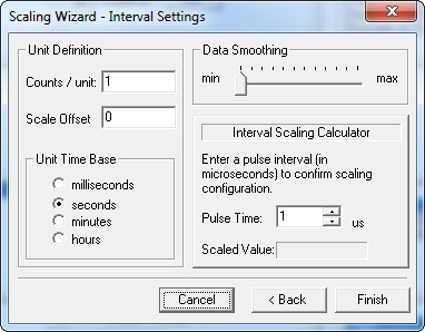
The interval scaling is done by setting 3 parameters in the Unit Definition box. An interval is essentially a velocity. Thus the resultant value will be some distance unit (e.g. inches, feet, revolutions, etc.) per some time unit (milliseconds, seconds, minutes, hours). The parameters are:
-
Counts / unit - This is the number of counts per velocity unit
-
Scale Offset - This is the constant amount to adjust the result by. Most of the time this is zero (0).
-
Unit Time Base - This is the time base for the unit being measured.
The other two boxes (Data Smoothing & Interval Scaling Calculator) are not used in the formula and will be explained after the interval-scaling examples below.
The easiest way to learn what settings to use is by example.
Interval Scale Example #1
An RPM (revolutions per minute) value is needed for a motor whose encoder is wired to the CTRIO input. The encoder attached to the motor and providing pulses to the CTRIO input is an 800-ppr (pulses per revolution) encoder.
-
Since the desired unit is RPM (revolutions per minute) a Unit Time Base of minutes is selected.
-
The encoder yields 800 pulses in 1 revolution. Thus if it made 1 revolution in 1 minute, that would yield 800 pulses in 1 minute's time. So if the CTRIO input sees 800 pulses in the time span of 1 minute, that would be 1 RPM. Thus, Counts / unit is equal to 800 (meaning 800 pulses per minute = 1 RPM).
-
Scale Offset is zero because when there are no pulses being generated, that would be 0 RPM (i.e. nothing needs to be added to the result.)
If these values are selected for the Unit Definition box they can be double-checked by using the embedded tool Rate Scaling Calculator. For instance, to see the Scaled Value result, plug in the following value:
-
Pulse Time: Since interval scaling is not calculating from a count (like rate scaling), but rather from a time value in microseconds, a pulse time must be entered instead of counts. If the encoder is generating 800 pulses per minute to get 1 RPM, this means it is generating (800 pulses per minute) / (60 seconds per minute) = 13.333 pulses per second. If rising edge to rising edge time period is being measured by the CTRIO input, then the period of the 13.333 pulses per second would be 1 / 13.333 pps = 75 milliseconds. Since the time being measured is in microseconds, this would be 75,000 microseconds.
-
Notice the result will yield 1 RPM.
Interval Scale Example #2
An fps (feet per second) value is needed for a conveyor belt. This conveyor belt is driven by a roller that is 10 inches in diameter. Attached to this roller is the same 800 ppr encoder. Thus:
-
Since the desired unit is fps (feet per second) a Unit Time Base of seconds is selected.
-
In order to figure out the Counts / unit the number of pulses received by the CTRIO when the conveyor belt moves 1 foot must be calculated. Since the roller is 10 inches in diameter and the belt is wrapped around it, the circumference must be calculated first. This is its diameter times pi.
10 inches x 3.14159 = 31.4159 inches
Thus when the roller rotates one full turn it has moved the conveyor 31.4159 inches. This 1 turn of the roller would also turn the encoder 1 full turn, and thus generate 800 pulses. Thus 800 pulses = 31.4159 inches of belt movement. Since the desired unit is feet per second and there are 12 inches per foot, then:
31.4159 inches / 12 in/ft = 2.618 feet.
This means when the roller turns 1 full turn, it has moved the belt 2.618 feet. Again, this 1 turn of the roller would also generate 800 pulses. Thus, 800 pulses = 2.618 feet of belt movement. So how many pulses will be seen if the belt only travels 1 foot?
800 pulses / 2.618 feet = 305.577 pulses per foot
Thus, Counts / unit is 305.577. Of course the CTRIO cannot see a fraction of a pulse, but a fraction can be used in the calculation. -
Scale Offset is zero, as usual.
If these values are selected for the Unit Definition box they can be double-checked by using the embedded tool Rate Scaling Calculator. For instance, to see the Scaled Value result, plug in the following value:
-
Pulse Time: Since interval scaling is not calculating from a count (like rate scaling), but rather from a time value in microseconds, a pulse time must be entered instead of counts. If the encoder is generating 305.577 pulses per second per foot, and rising edge to rising edge time period is being measured by the CTRIO input, then the period of 305.577 pulses per second would be 1 / 305.577 pps = 3.2725 milliseconds. Since the time being measured is in microseconds, this would be 3272.5 microseconds.
-
Notice the result will yield 1 fps.
The Data Smoothing box:
-
Data Smoothing - This is a slider adjustment that has 12 positions from min to max. Moving the slider toward max increases the number of running samples that are averaged together. This provides a smoothing affect in the interval scale value (i.e. so that it doesn't jump around). The positions from min to max represent the following number of samples:
-
1, 2, 3, 5, 7, 10, 13, 17, 21, 25, 30, 36 samples
See Also:
Module Configuration for H2-CTRIO, H2-CTRIO2 or T1H-CTRIO
CTRIO / CTRIO2 Instructions
CTDYNPOS - CTRIO Run Dynamic Position Mode
CTDYNVEL
- CTRIO Run Dynamic Velocity Mode
CTPLSADD - CTRIO Add Entry to PLS
CTPLSEDT
- CTRIO Edit PLS Entry
CTREGWR -
CTRIO Write Register
CTRUNPOS - CTRIO Run Position Mode
CTRUNVEL
- CTRIO Run Velocity Mode
CTTBLADD - CTRIO Add Entry to Preset Table
CTTBLEDT
- CTRIO Edit Preset Table Entry
CTRIO2 Only Instructions
CTAXCFG - CTRIO2
Axis Configuration
CTAXDYNP - CTRIO2 Axis Run Dynamic Position Mode
CTAXDYNV
- CTRIO2 Axis Run Dynamic Velocity Mode
CTAXTRAP - CTRIO2 Axis Run Trapezoid
CTAXLIMT
- CTRIO2 Axis Run Trapezoid w/ Limits
CTAXJOG - CTRIO2 Axis Jog Mode
Related Topics: