Topic: DMD0469

Program Check Error, Warning, and Messages Codes
| Code | Error | Warning | Message | Description |
|
89 |
|
|
Disconnected Module Configuration is referenced by the System Configuration where it MUST be connected.
Example: [Error] Module Config E089 Disconnected BX-SERIOx Module Configuration (SERIO_001) has at least one Comm Port (@SER_A_MODCLIENT) that is one of Modbus I/O Scanner's Modbus Client Devices
Why it's an issue: the Module Configuration is being used by a Device that must have the I/O module be in the system, for example, if the Modbus I/O Scanner is using a serial port on a BX-SERIO module, the Module Configuration for the BX-SERIO cannot be Disconnected.
|
|
| Code | Error | Warning | Message | Description |
|
90 |
|
The System Configuration contains a Module Configuration for a module that was present at one time but is not present now - this is known as a Disconnected Module. This message is letting you know the Module Configuration is still being downloaded as part of the System Configuration.
Example: Module Config M090 Disconnected Module (BX_04THM_001) is being downloaded as part of the System Configuration
When it's an issue: if the presence of the module is critical to the proper operation of the system.
When it might not be an issue: if the presence of the module is not currently critical and the module will be returned to the system at a later time and the Module Configuration will be reassigned to that module. But if the presence of the module is no longer required the disconnected Module Configuration is needlessly consuming space, adding confusion, and should probably be deleted.
|
||
|
91 92 |
|
|
You're attempting to use a feature was added in an updated Do-more Technology Version, but the currently connected PLC is running an older Do-more Technology Version that does not have support for the feature.
Example 1: Error - Update FW/Booter/GA - E091 Support for HSIO "Pulse Catch" on @HsCtrTmr1 device added in Do-more Technology Version 2.5, but this PLC is currently running DmT 2.2 (double-click to upgrade firmware) Example 2: Error - Update FW/Booter/GA - E901 Support for "Long Password Handling" (RX Password length 26; max 8) added in Do-more Technology Version 2.10, but this PLC is running DmT 2.9 (double-click to upgrade firmware)
Why it's an issue: the feature being used requires that you upgrade to new firmware or new boot loader support in the PLC before the project can be downloaded.
When it might not be an issue: if the new feature can be ignored by the PLC such that it will still allow the PLC to go to RUN mode.
|
|
|
93 |
|
The project contains one or more Locked code-blocks that are reporting error-level violations, but only a minimal amount of reporting is allowed because the code-block's security settings.
Example: [Message] Minimal reporting within locked code-block MyTask
Why it's an issue: the program check violation is caused by ladder logic is a code-block that is locked (password protected). The project cannot be downloaded to the PLC with errors, so the problem will probably require unlocking the code-block, which will require the password that was used to lock the code-block.
|
||
|
94 |
|
HighSpeed I/O Mapped: High Speed I/O cannot be mapped to a different address.
Example: [Error] On-board High Speed Inputs (X96 to X115) cannot be mapped; they must remain mapped starting at X0 [Error] On-board High Speed Outputs (Y104 to Y119) cannot be mapped; they must remain mapped starting at Y0
Why it's an issue: The on-board I/O of a BRX CPU cannot be remapped to different locations, they must remain at X0 - X31, and Y0 - Y31.
|
||
|
95 |
|
You're attempting to use a feature that requires a minimum FPGA / Booter version, but this PLC is currently running an older version that does not have the required support; this can only be checked while online.
Example: [Error] Update FW/Booter/GA E095 Support for "AXSCRIPT Instruction" requires FPGA Version 1.10 but this PLC is running FPGA Version 1.8
Why it's an issue: the feature requires an updated boot loader in the PLC before the feature can be utilized.
|
||
|
96 |
|
Based on the PLC's current Do-more Technology Version, an unrecognized I/O module was found in the system.
Example: [Error] Update FW/Booter/GA E096 Unknown BRX module ID(0) found in slot 1 in BRX Local I/O Master/BRX Local I/O (double-click to update Firmware)
Why it's an issue: the module requires new firmware or new boot loader support in the PLC before the I/O module will be recognized.
|
||
|
97 |
|
The System Configuration in the project is invalid and cannot be downloaded to a PLC.
Example: [Error] E097 Invalid System Configuration
Why it's an issue: without a valid System Configuration the entire project can be compromised, so you should stop using the project at once.
A crash dump file was also created, it will be at <Public Documents>\Do-more\DesignerX_Y\Bin\ DmDesigner_<version>_<date>_<time>.dmp, for example DmDesigner_2_5_1_198_20190219_213438.dmp. Please email a copy of that file along with a description of what you were doing in the software at the time the crash occurred to Support@HostEng.com. The more detail we have, the more likely it is that we can find what went wrong and caused the corruption.
|
||
|
101 |
|
|
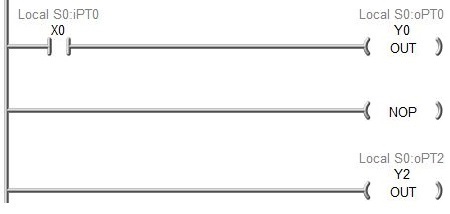
A rung is missing input logic so it's power-flow state will be based on previous rung's power flow state.
Example: W101 Rung MyProgram#6 is missing input logic, power-flow state will be based on previous rung's power flow state
In the example above, Output Coil Y2 will get its power-flow state from input X0 on rung 2 because there is no other interposing logic between Y0 and Y2.
When it's an issue: in the example above it is not obvious that both Y0 and Y2 are controlled by X0; removing the empty rung (NOP) will place both outputs in parallel on the same rung.
When it might not be an issue: the typical reason to have no interposing logic for an output is the output needs to be ON any time the code-block containing the logic is running. In the above example adding an normally-open contact ST1 ($On) to the rung will do this without involving the logic on the 2nd rung.
|
|
|
102 |
|
More than one instance of an instruction exists when only one instance is allowed.
Example: E102 Multiple PEERLINK instructions exist at addresses $Main@1 @3; only one PEERLINK allowed E102 Duplicate PEERLINK instruction exists at address $Main@1; only one PEERLINK allowed
Why it's an issue: some instructions are restricted to only one instance of the instruction in a project. More than one instance of an instruction of that type was found in the project so all but one instance of the instruction must be removed.
|
||
|
103 |
|
The Do-more Technology Version in CPU does not have support for the new instruction.
Example: E103 Do-more Technology Version 2.5 in CPU does not support the FIFOLOAD instruction; remove the instruction or upgrade firmware to at least Do-more Technology Version 2.6
Why it's an issue: the instruction requires CPU support that does not exist in the current version of the firmware. Either remove the instruction from the project or upgrade the CPU's firmware to a version that does contain the required support.
|
||
|
121 |
|
The project contains an instruction that is failing its internal validation.
When it's an issue: the validation error is specific to the instruction and must be corrected before the project can be downloaded to a PLC.
|
||
|
122 123 |
|
|
The project contains one or more Unassigned Nicknames. Do-more Designer can't download a project that has Unassigned Nicknames.
Example: M122 Program contains Unassigned Nicknames E123 Program contains Unassigned Nicknames
When it's an issue: all Unassigned Nicknames must be resolved before a project can be downloaded to a CPU. Use the Assign Nicknames utility to resolve them.
When it might not be an issue: an offline project can contain Unassigned Nicknames.
|
|
|
124 |
|
The project contains an instruction that is using a Device provided by an I/O module that is marked as Disconnected because the I/O module isn't present.
Example: E124 Disconnected Module Device (@HSIO_001_Axis1) used by AXCONFIG
Why it's an issue: the referenced Device is provided by an I/O module that must be present in the system before the project can be downloaded to the PLC.
|
||
|
125 126 |
|
|
As a result of Migrating a DirectLOGIC Project, the project contains one or more $DL* stub instructions which must be resolved.
Example: E126 DirectLOGIC Stub for "RADR" needs attention before downloading to PLC
When it's an issue: all $DL* instructions created by the Migrate DirectLOGIC Project utility must be removed before the project can be downloaded to a CPU. They can be deleted either because the functionality isn't required in a Do-more PLC, or replaced with instructions that accomplish the same task a different way then deleted.
When it might not be an issue: an offline project can contain $DL* instructions.
|
|
|
127 128 |
|
|
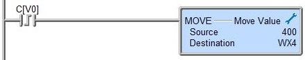
The project contains an array reference that is being used in an edge-triggered contact.
Example: E127 Array reference parameter C[V0] found within Leading Edge One-Shot Contact
When it's an issue: if the array reference changes while the code-block is executing the edge-triggered input will not be seen properly.
When it might not be an issue: if the array reference does not change while the code-block is executing .
|
|
|
129 |
|
The project has an instruction that is writing to the Raw Analog Output (WY) or to the Scaled Analog Input (RX) when that analog channel is configured for automatic scaling in the System Configuration.
Example: W129 MOVE parameter #2 writing to Raw Analog Output WY0, but that analog channel will overwrite WY0 because it has a predefined scale in the System Configuration (should write to Scaled Analog Output RY0)
Why it's an issue: the automatic scaling for the selected analog channel will always overwrite any instruction's attempt to write to the channel's raw memory location (if an output) or to the channel's scaled memory location (in an input).
|
||
|
130 |
|
The project contains an instruction that is writing to a High Speed Y that is bound to High Speed Output Function.
Example: W130 OUT parameter #1 writing to High Speed Output Y0 that is bound to @PWMOut1 - Pulse Width Modulation - Output: Y0 (instruction has no effect)
Why it's an issue: the High Speed functions will have complete control of any High-Speed output that it is using, any instruction that attempts to write to the output directly will have no effect.
|
||
|
131 |
|
An instruction is accessing an analog channel that is configured for 16-bit unipolar analog without the required :U cast operator.
Example: W131 MOVE "Destination" parameter referencing a 16 bit unipolar analog input (WX4) without Unsigned cast ":U"; should be WX4:U
When it's an issue: without the :U cast operator the value will be interpreted as a 15-bit signed number.
When it might not be an issue: instructions that are not aware of the underlying data format (MOVE, COPY, etc.) can operate properly because they will operate on all 16 bits of data without the :U cast.
|
||
|
132 |
|
The project contains an Immediate I/O instruction (INI, OUTI, RSTI, SETI) that is referencing an I/O point that is not capable of immediate I/O handling.
Example: E132 OUTI Y30 is not a valid Immediate Y discrete output (Y must be on-board BX MPU or on BX-HSIO module)
Why it's an issue: the I/O point cannot be turned ON or OFF immediately; this must be one of the on-board I/O points of a BRX PLC, or one of the I/O points on an BX-HSIO module.
|
||
|
133 |
|
Relational-Contact data-types are different between left & right side.
Example: M133 Equal-To Relational Contact real / integer mismatch and range of values for Left (1.17549e-038, 3.40282e+038) vs. Right (-2147483648, +2147483647)
When it's an issue:when the parameters on the left and right sides are different data types, like 16 bit unsigned integer vs. 32 bit signed integer.
When it might not be an issue: when the parameters on both the left and right sides are of the same data type.
|
||
|
134 |
|
Equality comparison between two 32-bit REAL values may not be accurate.
Example: M134 Equal-To Relational Contact - Equality comparison between two 32-bit REAL values may not be accurate.
When it's an issue: when comparing two Reals using an Equal-to comparative contact.
When it might not be an issue: when comparing two Reals using Less-Than or Greater-Than comparative contacts.
|
||
|
201 |
|
An element is being used in an instruction that requires the element also exist as a corresponding parameter in an other instruction, this is typically seen when a setup instruction for some PLC resource (Axis, Email, etc.) is missing.
Example: W201 "@Axis0" parameter in "AXJOG - Axis Jog Mode" does not exist as a corresponding parameter in any AXCONFIG primary instruction
When it's an issue:properly for the element to function in the first instruction the element must be used as a corresponding in the proper primary instruction.
When it might not be an issue: the instruction can be downloaded to the PLC but it wont operate without the primary instruction
|
||
|
202 203 |
|
|
An element is being used in an instruction that requires the element also be used as a corresponding parameter in a second instruction, and this element is found as the corresponding parameter in more than one other instruction. This is typically seen when there are multiple setup instruction for some PLC resource (Axis, Email, etc.).
Example: W202 @Axis0 in AXCONFIG used 1 other time: (AXCONFIG at $Main@15)
When it's an issue: if the element being referenced is a Stage Number the project can't be downloaded.
When it might not be an issue: the instruction can be downloaded to the PLC but it wont operate with multiple primary instructions.
|
|
|
204 |
|
A code-block exists without an instruction to execute it.
Example: M204 PROGRAM MyProgram exists without a RUN instruction to execute the PROGRAM
When it's an issue: all user-created code-blocks need an instruction to make them run; use the Run Program (RUN) instruction to execute a Program, use the Enable Task (ENTASK) to execute a Task.
When it might not be an issue: if the ladder logic in the code-block does not need to run then leaving the code-block in the project with no means of execution causes no harm, it only consumes space.
|
||
|
221 222 |
|
|
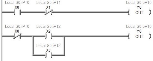
An element is being referenced in more than one Output coil. The last rung that contains the Output Coil will control the state of the element.
Example: M222 OUT Y0 coil duplicated 1 other time at $Main@11
In the example above, rung # 2 will drive the state of Output Y0 because it will immediately overwrite the state of rung #1.
When it's an issue: if the Output Coils are executed on the same PLC scan the rung that is scanned last will control the state of the output.
When it might not be an issue: if the Output Coils are in different code-blocks that don't run on the same scan, or in different Stages that don't run on the same scan, multiple Output Coils referencing the same element can work properly.
|
|
|
240 |
|
A single Modbus/TCP Client Device is being used to access more than one Modbus/TCP server.
Example: M240 Common Modbus/TCP Client device @IntModTCPClient used for multiple Servers <10.0.0.1> <10.0.0.2>; TCP overhead is minimized when one Do-more Modbus/TCP Device is created for each Modbus/TCP Server / Slave IP address
Why it's an issue: each time the MRX or MWX instruction is executed the Do-more CPU must establish the Modbus/TCP connection to the server, send the Read or Write function code, handle the returned data, then break down the Modbus/TCP connection to that server. If one MRX or MWX is already communicating with a Server, the second MRX or MWX will have to wait until the first has completed before the second can gain access to the Modbus/TCP Client Device. This problem is best solved by creating individual Modbus/TCP Client Devices for each Modbus/TCP server that will be used.
When it might not be an issue: using a single Modbus/TCP Client will always work, but the best performance can only be had when using a separate client device for each Modbus/TCP server.
|
||
|
241 |

|
The current configuration of the Master and Slave Axes prevent the Slave Axis from keeping up with - or overtaking - the Master Axis when it is in Follow mode, Gear mode, or running a Cam profile.
Example: W241 Slave Axis (@Axis1) in AXFOLLOW unable to keep up w/Master (@Axis0); Slave AXCONFIG MaxVel(1000) at $Main@13; Master AXCONFIG MaxVel(1000) at $Main@0; Slave must be faster than Master, slow down Master or speed up Slave
Why it's an issue: if the Slave's maximum velocity, acceleration, and gearing can't overtake or keep up with the Master axis, the AXFOLLOW, AXGEAR or AXCAM instructions will not be able to produce the desire result.
When it might not be an issue: if the Maximum Velocity or the Maximum Acceleration of the Master or Slave Axes are being changed in another instruction - for example AXSETPROP - then AXFOLLOW, AXGEAR or AXCAM instructions could perform as expected.
|
||
|
242 |
|
One or more pairs of FIFO / LIFO instructions are using the same Queue Struct or using the same data block as another pair of FIFO / LIFO instructions.
Example: W242 FIFOLOAD is a FIFO Queue instruction that uses Queue Struct FIFO_0, but this SAME Queue Struct is used as LIFO in 1 other Queue instruction: LIFOLOAD $Main@5
When it's an issue: each pair of FIFO / LIFO instructions needs exclusive use of Queue structure so that its structure members properly represent the contents of the queue's associated data block.
When it might not be an issue: if each pair of FIFO / LIFO instructions can be guaranteed exclusive use of Queue structure and its associated data block.
|
||
|
301 |
|
The Project contains duplicate LABEL instructions.
Example: E301 Duplicate LABEL (0) at addresses $Main@3 @8
Why it's an issue: LABEL instructions must be unique.
|
||
|
302 |
|
GOTO instruction is missing its target LABEL instruction.
Example: E302 GOTO 1 missing corresponding LABEL 1
Why it's an issue: a GOTO instruction must have a single valid LABEL instruction as its target.
|
||
|
303 |
|
GOTO instruction cannot target a LABEL in a different Stage.
Example: E303 Cannot GOTO a LABEL (at $Main@19) in a different Stage
Why it's an issue: a GOTO instruction can only target a LABEL that is in the same Stage.
|
||
|
304 |
|
The project contains a LABEL instruction that is not the target of a GOTO instruction.
Example: M304 LABEL 2 missing corresponding GOTO
When it might not be an issue: an unused LABEL needlessly consumes space in the project.
|
||
|
305 |
|
A GOTO instruction cannot target a LABEL instruction in a different code-block.
Example: E305 Cannot GOTO a LABEL (at MyProgram@0) in a different code-block
Why it's an issue: targeting a LABEL in a different code-block potentially allows moving program execution into a code-block that is not enabled (Task) or not running (Program), and if so, the PLC scan would get hung up at that point.
|
||
|
311 312 |
|
An end-of-loop instruction was found with no matching start-of-loop or instruction or it is paired with incorrect start-of-loop instruction, or a start-of-loop instruction was found with no matching end-of-loop instruction.
Example: E311 End-of-loop (NEXT) missing corresponding start-of-loop (FOR) E312 Start-of-loop (FOR) missing corresponding end-of-loop (NEXT)
Why it's an issue: all looping constructs require a matched set of starting and ending instructions (For / Next, While / Wend, Repeat / Until Goto / Label).
|
||
|
313 314 |
|
|
An instruction was found inside a loop that is not allowed there.
Example: E313 SG not allowed within a loop (FOR at $Main@2) M314 JMP found within loop (FOR at $Main@2)
Why it's an issue:Stage (SG) and Converge Multiple Stages (SGCONVRG) instructions cannot exist within a loop because they .
When it might not be an issue:Jump to Stage (JMP), Indexed Jump (JMPI), Jump to Multiple Stages (SGDIVRG), and any instruction that has the option to Jump to Stage On Success or On Error, and the Delta contact are allowed within a loop, but probably won't operate as expected.
|
|
|
315 |
|
|
An instruction with an edge-triggered input is being used within loop.
Example: W315 Clocked/edged instruction (Leading Edge One-Shot Contact) used within loop (FOR at $Main@2)
Why it's an issue: edge-triggered inputs need to see an OFF-to-ON or ON-to-OFF transition on successive scans, the ladder logic inside a loop runs to completion on a single scan which would never allowed a transition to be seen.
|
|
|
316 |
|
A GOTO instruction is not allowed inside of a loop.
Example: E316 Cannot GOTO a LABEL (at $Main@13) into or out of a FOR/NEXT loop
Why it's an issue: GOTO instructions are not allowed within a loop; use an Exit Loop (BREAK) instruction to get out of a loop while it is running.
|
||
|
317 |
|
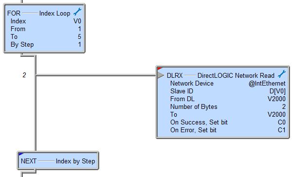
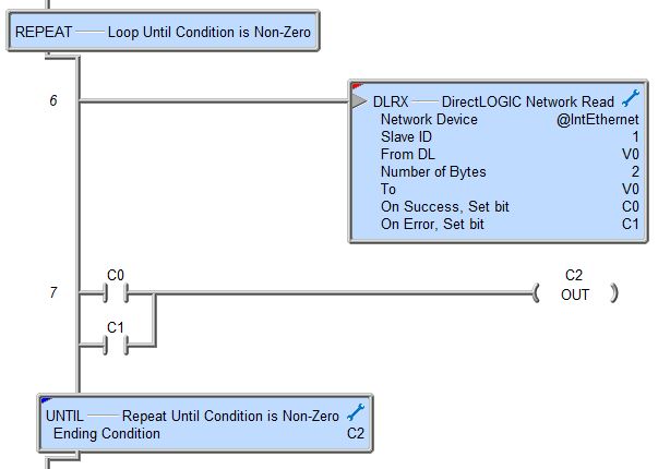
The project contains an asynchronous instruction within a loop. Asynchronous instructions - by definition - require processing from PLC resources that run asynchronously to the PLC scan, these are typically communication resources which take multiple PLC scans to complete, but this also includes timer based resources which require processing at the end of each PLC scan. Extra care must be taken when using looping instructions to execute asynchronous
Example: W317 Asynchronous instruction (DLRX) found within loop (FOR at $Main@0)
Why it's an issue: FOR / NEXT loops use a count as the ending event, so the passes through the loop occur as quickly as the code-block's TimeSlice value will allow. And this happens irrespective of the state of the asynchronous instruction.
In the example below you might think the FOR / NEXT loop will cycle through DLRX attempts to Slave IDs 1 through 5. The first pass through the loop will begin the communication request for Slave ID #1, but when the TimeSlice expires, the loop will want to generate a communication request to Slave ID #2 without waiting on the first comm request to be completed. The same will happen for the remaining Slave IDs.
When it might not be an issue: if the On Success / On Error indications are being used to exit the loop.
In the example below the Repeat / Until loop will continue to run until the DLRX instruction completes - either successfully or not, then the loop will end.
|
||
|
318 |
|
The project contains an instruction outside of a loop that must exist within a loop.
Example: E318 BREAK must exist within a loop (like FOR / NEXT or WHILE / WEND)
Why it's an issue: these instructions cannot perform their intended task unless they are placed within loops.
|
||
|
331 |
|
The project contains an asynchronous instruction that is being used in a code-block which contains one or more yielding instructions.
Example: M331 Asynchronous instruction TMR used in code-block with 4 yielding instructions (NEXT at @115 NEXT at @159 NEXT at @208 NEXT at @287).
Why it's an issue: yielding instructions allow the PLC scan to process a portion of the passes through a looping instruction then allow the PLC to leave the code-block and come back on the next PLC scan. When the PLC leaves the code-block the TMR does not accrue time.
|
||
|
401 |
|
It is not recommend that a code-block contain a SUSPEND instruction that targets itself.
Example: W401 SUSPEND MyProgram not recommended within its own code-block (no easy way to un-SUSPEND self)
When it's an issue: if a code-block SUSPENDs itself, that code-block cannot un-suspend itself, the proper method it to have the SUSPEND instruction in a different code-block.
When it might not be an issue: if the code-block will never be un-suspended, or a Restart Program or Task (RESTART) instruction in a separate code-block will be used to make the code-block run again.
|
||
|
402 |
|
The project contains a RUN or ENTASK instruction that targets the code-block that contains the instruction.
Example: W402 Found RUN MyProgram within its own code-block (MyProgram)
When it's an issue: having a running code-block execute a Run Program (RUN) or Enable Task (ENTASK) that targets itself will have no effect.
|
||
|
403 |
|
The project contains a HALT instruction for a code-block that utilizes fully-asynchronous instruction.
Example: W403 Using HALT on a code-block MyProgram that utilizes fully-asynchronous instruction(s)
Why it's an issue: asynchronous instructions typically use devices that must be locked / unlocked by the instruction. If the asynchronous instruction is running when the HALT instruction is executed, the instruction cannot unlock the device, meaning the device will remain locked for any other instruction that needs to use it.
When it might not be an issue: if the asynchronous instruction isn't locked when the HALT executes, there's no problem.
|
||
|
404 |
|
The project contains an instruction that is not allowed in the type of code-block where it was located.
Example: E404 SG box will not execute correctly in a Task code-block
Why it's an issue: the instruction must be removed from the code-block, or the code-block type must be changed to one that's appropriate.
|
||
|
405 |
|
The project contains instructions after an unconditional RET or END instruction that will never execute.
Example: E405 Code exits after unconditional END instruction; code will never execute
Why it's an issue: the instructions after the RET or END will never be scanned need to be placed before the RET or END.
|
||
|
411 |
|
The project contains an instruction in a user-created code-block that can only exist in $Main code-block.
Example: E411 PEERLINK can only exist in $Main code-block
Why it's an issue: this instruction must be moved to the $Main code-block before the project can be downloaded.
|
||
|
412 |
|
The project contains an instruction that can only exist in a Program code-block that was found in a non-Program code-block.
Example: E412 SG found in a TASK code-block; can only exist in a PROGRAM code-block
Why it's an issue: this instruction must be removed from the non-Program code-block before the project can be downloaded.
|
||
|
413 |
|
The project contains an instruction in $Main that can't exist in $Main.
Example: E413 EXIT not permitted in $Main code-block
Why it's an issue: this instruction must be removed from $Main before the project can be downloaded.
|
||
|
421 |
|
A Stage bit in one Program code-block cannot be modified by ladder logic in a different Program code-block.
Example: E421 Stage bit (MyProgram.S0) cannot be modified by logic in a different PROGRAM code-block ($Main)
Why it's an issue: Stage instructions can only reference Stages that are in the same code-block.
|
||
|
422 |
|
The project contains an instruction in a Stage that will not operate properly in a Stage.
Example: E422 PEERLINK cannot be in a Stage (SG S0 at @0)
Why it's an issue: the instruction must always be part of the PLC scan so it cannot be placed where it could potentially not be included in the scan.
|
||
|
423 |
|
The project contains an instruction that must be within a Stage outside of a Stage.
Example: E423 JMP must be within a Stage
Why it's an issue:Jump to Stage (JMP), Indexed Jump (JMPI), and Jump to Multiple Stages (SGDIVRG) instructions must be within a Stage because they enable the target Stage AND disable the stage that contains the instruction.
|
||
|
424 |
|
A Stage that is non-retentive contains an Output Coil that is using a retentive element.
Example: W424 Using retentive element (C0) in OUT coil within a non-retentive stage (MyProgram.S2)
Why it's an issue: if the state of the element being using in the Output Coil truly needs to be maintained through a power failure then the Stage where that Output is located needs to be set as retentive as well so that the Stage will be ON when power is restored.
When it might not be an issue: if the Output coil doesn't need to be retentive it should use an element that is not marked as retentive.
|
||
|
425 |
|
A Stage contains an instruction that is using an element as a parameter that might not work as expected.
Example: W425 Recommend not using <element> within a Stage.
Why it's an issue: if an instruction is using a memory element as the parameter in an OUT coil; for example OUT( C[V0] ). This could be a problem since the termination behavior may be different if the array index [V0] changes between the scan when the instruction was enabled and the Termination scan.
When it might not be an issue: if the array index does not change between the scan when the instruction was enabled and the Termination scan.
|
||
|
451 452 |
|
A Time-based instruction is being used in a edge-enabled task, or a continuously enabled Task with a non-zero time interval.
Example: W451 Time-based instruction (TMR) used in edge-enabled task (ENTASK MyTask at $Main@0) W452 Time-based instruction (TMR) used in a continuously-enabled task with a non-zero interval (ENTASK MyTask at $Main@0)
When it's an issue: the Timers will only accrue time when the Task that contains the Timer is enabled, which in this case is only one scan.
|
||
|
453 454 |
|
A fully-asynchronous instruction is being used in an edge-enabled task, or a continuously-enabled task with a non-zero interval.
Example: W453 Fully-asynchronous instruction (MRX) used in edge-enabled task (ENTASK MyTask at $Main@0) W454 Fully-asynchronous instruction (MRX) used in a continuously-enabled task with a non-zero interval (ENTASK MyTask at $Main@0)
When it's an issue: the fully asynchronous instruction will only run while the Task containing the instruction is enabled, which in this case is one PLC scan. When the Task ends the instruction will be terminated so the device being used by the instruction will not stay locked.
|
||
|
455 456 |
|
|
A partially asynchronous instruction used in edge-enabled task or a continuously-enabled task with a non-zero interval.
Example: W455 Partial-asynchronous instruction (CNT) used in edge-enabled task (ENTASK MyTask at $Main@0) W456 Partial-asynchronous instruction (CNT) used in a continuously-enabled task with a non-zero interval (ENTASK MyTask at $Main@1)
When it's an issue: partially-asynchronous instructions - also known as Multi-Scan instructions - require multiple successive scans to operate properly; edge-triggered Tasks will only run one scan each time the ENTASK is enabled.
|
|
|
457 458 |
|
An instruction that has an input that is clocked or edge-driven is used in a Task that is itself edge-enabled, or a continuously-enabled task with a non-zero interval.
Example:
M458 Clocked / edged instruction (Leading Edge One-Shot Contact) used in a continuously-enabled task with a non-zero interval (ENTASK MyTask at $Main@0)
When it's an issue: instructions with an edge-triggered input need to see an OFF-to-ON transition to register as a legitimate input. These instructions require a minimum of two scans to operate properly; one scan to see the OFF state, and a second scan to see the ON state. Edge-triggered Tasks will only run one scan each time the ENTASK is enabled.
When it might not be an issue: if the input logic is ON when the Task is enabled the instruction will see that input as having made the require OFF-to-ON transition.
|
||
|
459 |
|
The same Task is being enabled with both an edge-enabled ENTASK instruction and an interval-enabled ENTASK instruction.
Example: W459 Edge-Enabled ENTASK MyTask exists with 1 Interval-Enabled ENTASK MyTask instruction at address $Main@5
When it's an issue: if the ladder logic in the Task is written to work with as an edge-triggered code-block, it probably wont work as a power-flow based Task.
|
||
|
460 |
|
The same Task is being enabled by multiple interval-enabled ENTASK instructions with different intervals.
Example: W460 Other continuous / interval-ed ENTASK MyOtherTask exist at addresses $Main@10 @14
When it's an issue: the interval value will be set by the last ENTASK instruction that is executed.
When it might not be an issue:if the intention to change the interval value at runtime is going to used mutually exclusive input logic it could work. A better way would be to have one ENTASK instruction that uses a variable memory location for the interval.
|
||
|
461 |
|
The project contains an edge-triggered Task which has a counting instruction with an input that requires an OFF-to-ON transition.
Example: W461 Full OFF-to-ON Transition Input Leg counting instruction (CNT) used in edge-enabled task (ENTASK MyTask at $Main@0)
When it's an issue: an OFF-to-ON transition requires at least two scans which is not possible in an edge-triggered Task because it runs to completion on a single scan.
|
||
|
501 |
|
The project contains a Subroutine that is missing the required Return Back to Call (RET) instruction at the end of the code-block.
Example: E501 Subroutine "MySubroutine" missing required "RET - Return Back to CALL" at end of code-block (double-click to add it)
When it's an issue: subroutines must have a RET instruction as the last instruction in the code-block.
|
||
|
521 |
|
|
The project contains a High Speed discrete output that is being turned ON / OFF with a non-immediate instruction in an Interrupt Service Routine.
Example: M521 High Speed Discrete Output (Y0) set within non-Immediate instruction (OUT Y0) in Interrupt-Service-Routine (MyISR)
Why it's an issue: using an OUT, RST, or SET instruction in an Interrupt Service Routine - instead of their immediate counterparts OUTI, RSTI, and SETI instruction - will still turn the output ON / OFF at the bottom of the scan, not at this point in the scan.
|
|
|
522 |
|
|
The project contains an immediate I/O instruction in a code-block that is not an Interrupt Service Routine.
Example: M522 Immediate I/O instruction (OUTI) inside NON-Interrupt-Service-Routine (Subroutine MySubroutine)
Why it's an issue: using the INI, OUTI, RSTI, or SETI instructions in a Program or Task makes them subject to the PLC's scan time, which is probably not the desired effect.
|
|
| The 700 series of codes all pertain to features that have been added to the Do-more PLCs after their initial release. They all require that you remove the offending instruction, modify the parameters of the instruction (if possible), or upgrade the PLCs firmware to added the required support for the feature.
|
||||
|
701 |
|
Do-more Technology Version in the CPU only supports Edge-Triggered Input-Leg (not Power-Flow-Enabled) in an instruction; modify the instruction or upgrade the PLC's firmware.
Minimum Do-more Technology Version required: v1.1
|
||
|
702 |
|
Do-more Technology Version in the CPU does not support ONLY Swap Bytes or ONLY Swap Words on DWORD sized memory in a PUBLISH, or SUBSCRIB instruction; modify the instruction, or upgrade the PLC's firmware.
Minimum Do-more Technology Version required: v1.1
|
||
|
703 |
|
Do-more Technology Version in the CPU does not support clearing bit-sized elements in a Clear Memory Range (MEMCLEAR) instruction; modify the instruction, use a Reset Range (RSTR) instruction, or upgrade the PLC's firmware.
Minimum Do-more Technology Version required: v1.1
|
||
|
704 |
|
Do-more Technology Version in the CPU does not support a variable Modbus parameter in a Modbus Network Read MRX, or Modbus Network Write (MWX) instruction; use a constant value, or upgrade the PLC's firmware.
Minimum Do-more Technology Version required: v1.1
|
||
|
705 |
|
Do-more Technology Version in the CPU does not support a variable parameter in a SNTP Client (NETTIME) instruction; use a constant value, or upgrade the PLC's firmware.
Minimum Do-more Technology Version required: v1.1
|
||
|
706 |
|
Do-more Technology Version in CPU does not support a variable networking parameter in a DirectLOGIC Network Read (DLRX) or DirectLOGIC Network Write (DLWX) instruction; use a constant value, or upgrade the PLC's firmware.
Minimum Do-more Technology Version required: v1.1
|
||
|
707 |
|
Do-more Technology Version in CPU does not support \"ipaddr\" format in \"FmtInt()\" print script command in the Print to String (STRPRINT) instruction.
Minimum Do-more Technology Version required: v1.3
|
||
|
708 |
|
Do-more Technology Version in CPU does not support accessing the specified register in Read Device Register (DEVREAD) or Write Device Register (DEVWRITE) instruction.
Minimum Do-more Technology Version required: v1.1
SERIAL_BAUD_RATE SERIAL_DATA_BITS SERIAL_PARITY SERIAL_XMIT_CTRL SERIAL_KSEQ_STATION SERIAL_MODBUS_UNITID SERIAL_MODBUS_RETRIES
Minimum Do-more Technology Version required: v1.3 SMTP_AUTH_MODE SMTP_AUTH_USER SMTP_AUTH_PASSWORD
Minimum Do-more Technology Version required: v1.4 DSMTP_TIMEOUT
Minimum Do-more Technology Version required: v2.0 POM_PORT_MODE
Minimum Do-more Technology Version required: v2.3 SMTP_SERVER_NAME MQTT_PORT MQTT_TIMEOUT MQTT_PASSWORD MQTT_SERVER_NAME MQTT_USERNAME MQTT_WILL_TOPIC MQTT_WILL_PAYLOAD
Minimum Do-more Technology Version required: v2.6 MQTT_CLIENTID
|
||
|
890 |
|
The CTRIO file with the specified file number is the wrong type for the instruction.
Example: E890 @CTRIO_001_Out2 CTRIO's file system does not contain a file at file number 1 compatible with the CTTBLLD instruction
Why it's an issue: the file being loaded from the CTRIO's internal file system must be compatible with the instruction that will use the file.
|
||
|
901 - 999 |
|
Reserved.
|
||


See Also:
Related Topics:
The Ladder Editor: Compiler Errors
Do-more Designer Programming Environment