Topic: DMD0515

JMPI - Indexed Jump
The Indexed Jump (JMPI) instruction is used to jump to a specific stage within a contiguous range of stages. The instruction uses the Index value to select one of the stages within that range, and then transition to the selected stage. The Last / Exception Stage in the defined range is the error handling (exception) stage. Any time the Index value is not within the defined range of stages, the Last / Exception Stage will be selected.
For example, if the Index has a value of 7, andFirst Stage is S12, and the Last / Exception Stage is S21, then the instruction would jump to Stage S19 (S12 + 7). If the value in Index had been larger than the range created in the instruction (e.g. value of 11; S12 + 11 = S23) or a negative value, then the instruction would jump to the Last / Exception Stage (21).
It is important to note that when this instruction is executed, it does NOT cause an immediate move to the target stage; it simply enables the target stage. The effect of this instruction will occur the next time the target stage is normally processed as part of the CPU's scan. This means if the target stage is "below" this stage in the Program, the target stage will execute on the same scan as the JMPI instruction; if the target stage is "above" this stage in the Program, the target stage will execute on the scan following the JMPI instruction.
The effect of this instruction will occur the next time the affected stages are normally processed as part of the CPU's scan. When a stage becomes disabled, on the next scan the disabled stage executes Termination Logic where Output (OUT) coils are turned OFF and Timers are reset.
Like all of the other stage programming instructions this one must be placed in a Program; stage instructions cannot be placed in a Task, a Subroutine, or an Interrupt Service Routine. Stage programming instructions can only reference stages in the same Program code block, they cannot reference stages in a different Program code block.
To switch between displaying the fully qualified stage reference ($Main.S0) and the abbreviated name (S0), go to the View -> Options -> Ladder Tab -> Misc. Options and check the 'Abbreviate Stage Names (Use S0 over $Main.S0)' option.
For a complete discussion on Stage Programming and how to use the Stage programming instructions effectively, refer to the Help Topic on Stage Programming Concepts.
Parameters:
Note: Use the F9 key or click the 'three dot box' at the right edge of the parameter field to open the Default Element Selection Tool (the Element Picker or the Element Browser) or use the Down-Arrow key (Auto-Complete) on any parameter field to see a complete list of the memory locations that are valid for that parameter of the instruction.
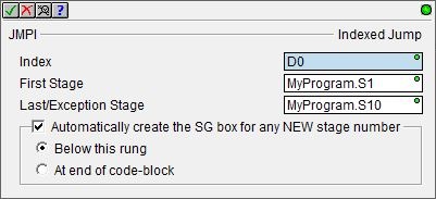
Index is the memory location where the Index value is located. This can be any readable numeric location.
First Stage is the first stage in the range of stages. The First Stage can only be a stage in the same Program; it cannot reference a stage in a different Program. The First Stage reference can be entered using its fully qualified name (for example MyProgram.S0 through MyProgram.S126) or simply its stage number (for example S0 through S126).
Last / Exception Stage is the final stage in the contiguous range of stages. The Last Stage can only be a stage in the same Program; it cannot reference a stage in a different Program. The Last / Exception Stage reference can be entered using its fully qualified name - for example MyStage.S0 through MyStage.S127 - or simply its stage number - for example S0 through S127.
Automatically create the SG box for any NEW stage number: if a First Stage number, or Last Stage number, or any stages in the contiguous range between them do not exist, those Stages can be automatically created.
- Below this rung means the First stage will be created on a new run following this instruction; as many new rungs as required for the intermediate stages and Last / Exception stage will be added immediately after that.
- At end of code-block means the First stage will be created as the last rung of the Program; as many new rungs as required for the intermediate stages and Last / Exception stage will be added after that.
Status Display:
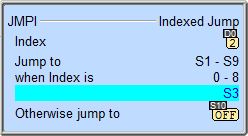
The status display shows the current Index value and which Stages in the contiguous range are enabled .
See Also:
JMPI - Indexed Jump
SGRSTI - Indexed Disable Stage
SGRSTR - Disable Range of Stages
SGDIVRG - Jump to Multiple Stages
SGCONVRG - Converge Multiple Stages to SG
Related Topics:
Stage Programming Concepts
Example 1 - A Simple 2-State Process
Example 2 - A Lamp On / Off Controller
Example 3 - A Garage Door Opener
Review - Steps to Writing Successful Stage Programs
Example 1 of 2:
Description of an Indexed Jump (JMPI) Diagram:
This is a stage diagram of a simple sequence control that would utilize a JMPI (Indexed Jump) instruction. This diagram would fill a vessel with a different color of material depending on the Color setting, cook its contents and then drain and repeat if necessary. It is good to imagine the sequence before actually writing the ladder logic.
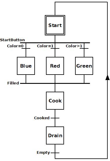
Initially stage 'Start' waits for StartButton to come ON. When StartButton comes ON, the process transitions to either stage 'Blue', 'Red' or 'Green' depending on the value in the Color variable. In the case where the Color is of any other value than 0 or 1, stage 'Green' is assumed.
Each color fill stage fills the vessel. Once the vessel is full (Filled = ON), the process transitions to stage 'Cook'.
Stage 'Cook' cooks for a period of time. Once the time to cook is complete (Cooked = ON), the process transitions to stage 'Drain'.
Stage 'Drain' empties the contents of the vessel. Once the vessel is drained (Empty = ON), the process transitions back to stage 'Start' to repeat as necessary.
Ladder Logic for the above Stage Diagram:
This is a ladder logic equivalent to the above stage diagram.
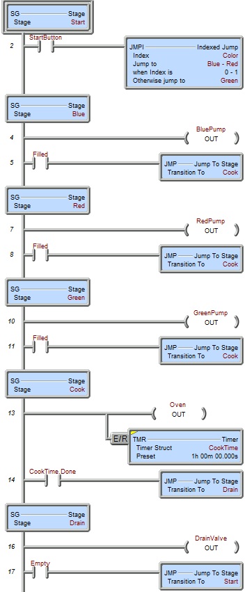
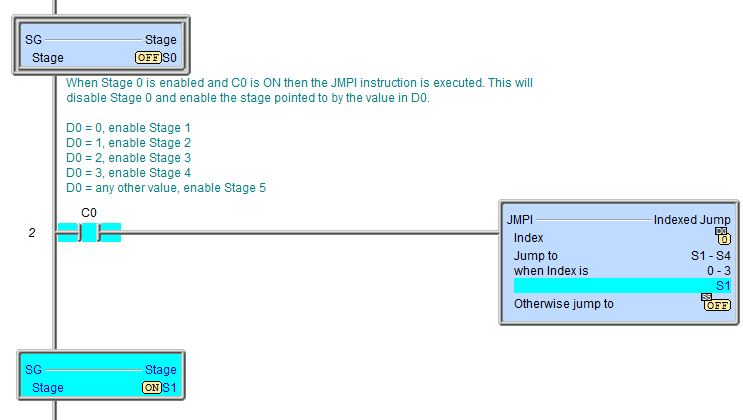
Once the Program code block containing this stage is first enabled to run, the initial stage ('Start') will be enabled because it is the initial stage (designated by the double border). None of the ladder logic in other stages is executed; only Rung 2. Once StartButton comes ON the JMPI (Indexed Jump) instruction is executed. This instruction disables stage 'Start', and enables stage 'Blue' or 'Red' or 'Green' depending on the value stored in Color. If Color = 0, stage 'Blue' is enabled. If Color = 1, stage 'Red' is enabled. Any other value for Color will enable stage 'Green'.
Note: The SG instructions have rung numbers but they are hidden by the SG box.
If stage 'Blue' is enabled, BluePump turns ON to power the pump motor so that blue product will begin to fill the vessel. Once the Filled indicator comes ON, the JMP instruction is executed. This instruction disables stage 'Blue' and enables stage 'Cook'. Also, since stage 'Blue' is now disabled, all OUT coils in that stage will be turned OFF (i.e. BluePump will go OFF).
If stage 'Red' is enabled, RedPump turns ON to power the pump motor so that red product will begin to fill the vessel. Once the Filled indicator comes ON, the JMP instruction is executed. This instruction disables stage 'Red' and enables stage 'Cook'. Also, since stage 'Red' is now disabled, all OUT coils in that stage will be turned OFF (i.e. RedPump will go OFF).
If stage 'Green' is enabled, GreenPump turns ON to power the pump motor so that green product will begin to fill the vessel. Once the Filled indicator comes ON, the JMP instruction is executed. This instruction disables stage 'Green' and enables stage 'Cook'. Also, since stage 'Green' is now disabled, all OUT coils in that stage will be turned OFF (i.e. GreenPump will go OFF).
When stage 'Cook' is enabled, Oven turns ON to power the heaters so that regardless of the color of the product, it will be cooked. CookTime timer also starts timing immediately. When CookTimer cooks for 1 hour the JMP instruction is executed. This instruction disables stage 'Cook' and enables stage 'Drain'. Also, since stage 'Cook' is now disabled, all OUT coils in that stage will be turned OFF (i.e. Oven will go OFF) and all timers will be reset (i.e. CookTime will be reset).
When stage 'Drain' is enabled, DrainValve turns ON to open the drain valve at the bottom of the vessel to allow the cooked product to drain. Once the Empty indicator comes ON, the JMP instruction is executed. This instruction disables stage 'Drain' and enables stage 'Start'. Also, since stage 'Drain' is now disabled, all OUT coils in that stage will be turned OFF (i.e. DrainValve will go OFF).
Since stage 'Drain' stage loops back to stage 'Start', this process will be repeated until the Program code block running this ladder logic is halted.
Example 2 of 2: