Topic: DMD0551
![]()
CTRIO Module Configuration - Input Filters
Note:The Input Filters are only used by the CTRIO2 module. Their settings have no effect for the CTRIO module.
To get to the CTRIO Module Configuration - Input Filters:
-
Follow this menu path: PLC --> System Configuration --> Module Configuration(s). This pulls up the System Configuration dialog.
-
Double-click on the CTRIO to configure. This pulls up the Edit CTRIO/CTRIO2 Configuration dialog.
-
Press the <Input Filters> button.
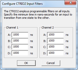
The digital input filters are used to filter out unwanted noise and are analogous to hardware filtering only much better and easier to tune. By default all channels are set to 1000 nanoseconds, however, values from 1 to 819,187 can be entered. The following questions will be discussed below:
1. What does the value of the Input Filter mean?
As the dialog itself states, "Specify the minimum time in nanoseconds for an input to transition from one state to the other." For example, the default value is 1000 nanoseconds. This has the basic meaning that the input of the CTRIO2 must be ON for 1000 nanoseconds before the CTRIO2 will see it as being ON and vise versa. Consequently this means if an input signal is changing faster than 1000 nanoseconds the CTRIO2 input will not see it.
2. How does the Input Filter generally work?
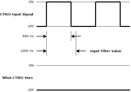
Though this is not technically accurate, the approximate behavior is shown in the diagram above. Notice the CTRIO Input Signal is only ON for 800 nanoseconds, which is 20 nanoseconds short of the Input Filter Value. Thus What the CTRIO Sees is no signal change.
A square wave that is ON for 800 ns and OFF for 800 ns has a period of 1600 ns, which is a frequency of 625 KHz. Thus, in this example, the 625 KHz signal is completely rejected and "filtered" out.
But this is only an approximation, as will be seen. What is technically happening is depicted better in the next diagram.
3. Technically, what is actually happening?
Technically, the way the Input Filter works is that the CTRIO2 samples its input at a fixed clock rate of 12.5 nanoseconds. Each time the input is seen as ON it increments its input filter counter. Each time the input is seen as OFF it decrements its input filter counter. When this counter cumulatively reaches the Input Filter value, the CTRIO2 registers this input as being ON. Once it has registered the input as being ON, it now must be cumulatively decremented back to 0 before it will register the input as going back OFF.
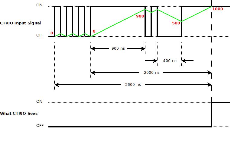
In the diagram above, the Input Filter is set to 1000 nanoseconds. The accumulating value of the input filter counter is shown by the green line. The red numbers show its value at specific intervals. So for the noisy CTRIO Input Signal as shown, notice when it is ON the input filter counter value is increasing. When the CTRIO Input Signal is OFF the input filter counter value is decreasing. What CTRIO Sees is an ON only when the input filter counter has accumulated 1000 nanoseconds worth of time ON.
4. What value should be set for the Input Filter?
If it is not certain the maximum frequency that will be wired to the CTRIO2 input, then, unless there is a problem with noise, the default values of 1000 nanoseconds are best assuming the CTRIO2's rated maximum input frequency of 250 KHz (250,000 Hz). This setting allows a 25% duty cycle signal to pass.
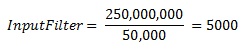
If,however, the maximum frequency is known and filtering is desired, then the best formula for determining that value is:
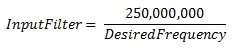
Thus, if the maximum input frequency was 50 KHz (50,000 Hz), then...
See Also:
Module Configuration for H2-CTRIO, H2-CTRIO2 or T1H-CTRIO
CTRIO / CTRIO2 Instructions
CTDYNPOS - CTRIO Run Dynamic Position Mode
CTDYNVEL
- CTRIO Run Dynamic Velocity Mode
CTPLSADD - CTRIO Add Entry to PLS
CTPLSEDT
- CTRIO Edit PLS Entry
CTREGWR -
CTRIO Write Register
CTRUNPOS - CTRIO Run Position Mode
CTRUNVEL
- CTRIO Run Velocity Mode
CTTBLADD - CTRIO Add Entry to Preset Table
CTTBLEDT
- CTRIO Edit Preset Table Entry
CTRIO2 Only Instructions
CTAXCFG - CTRIO2
Axis Configuration
CTAXDYNP - CTRIO2 Axis Run Dynamic Position Mode
CTAXDYNV
- CTRIO2 Axis Run Dynamic Velocity Mode
CTAXTRAP - CTRIO2 Axis Run Trapezoid
CTAXLIMT
- CTRIO2 Axis Run Trapezoid w/ Limits
CTAXJOG - CTRIO2 Axis Jog Mode
Related Topics: