Topic: DMD0070

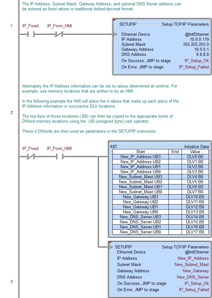
SETUPIP - Setup TCP/IP Parameters
The Setup TCP/IP Parameters (SETUPIP) instruction is used to configure the TCP/IP networking parameters for the on-board Ethernet port of a Do-more CPU, a BX-P-ECOMLT POM, or a BX-P-ECOMEX POM.
A copy of the current TCP/IP Address for the on-board Ethernet port is stored in $IPAddress (DST18), its current Subnet Mask in $NetMask (DST19), and its current Gateway Address in $Gateway (DST20). Any time this instruction completes successfully these three memory locations are updated.
If a BX-P-ECOMEX (Secondary Ethernet port) is installed in the POM slot, a copy of its current TCP/IP Address is stored in $Eth2IpAddress (DST62), its current Subnet Mask in $Eth2Netmask (DST63), and its current Gateway Address in $$Eth2Gateway (DST64). Any time this instruction completes successfully these three memory locations are updated.
If a BX-P-ECOMLT is installed in the POM slot, a copy of its current TCP/IP Address is stored in $POMIpAddress (DST55), its current Subnet Mask in $POMIpNetmask (DST56), and its current Gateway Address in $POMIpGateway (DST57). Any time this instruction completes successfully these three memory locations are updated.
Note: when updating the on-board Ethernet Port or the BX-P-ECOMLT, this instruction writes to the ROM in the Do-more CPU. As such, this instruction may take several seconds of time to complete. It is also important that this instruction NOT be executed more than is necessary because the ROM chip in the Do-more CPU has a limited number (~100K) of write cycles.
Parameters:
Note: Use the F9 key or click the 'three dot box' at the right edge of the parameter field to open the Default Element Selection Tool (the Element Picker or the Element Browser) or use the Down-Arrow key (Auto-Complete) on any parameter field to see a complete list of the memory locations that are valid for that parameter of the instruction.
Ethernet Device selects which Ethernet device to configure:
@IntEthernet is the on-board Ethernet port.
@POM (ECOMEX) is a BX-P-ECOMEX installed in the POM slot.
@POM (ECOMLT) is a BX-P-ECOMLT installed in the POM slot.
Note: click the gear symbol at the right end of the Ethernet Device selection to open the appropriate configuration dialog where the options for that device can be changed.
Note: If the Ethernet device is the on-board Ethernet port or the BX-P-ECOMLT this instruction changes the IP configuration stored in FLASH memory, making the changes persistent across a power-cycle. If the Ethernet device is the BX-P-ECOMEX this instruction only changes the working copy in RAM, so it is NOT persistent across a power-cycle. You must use the POM configuration dialog in the System Configuration to make persistent changes to the BX-P-ECOMEX POM.
On BRX CPUs, you can enable the Obtain an IP Address automatically (use DHCP) option to have the selected Ethernet device get it's TCP/IP address configuration from a DHCP server.
Enable the Obtain an IP Address automatically (use DHCP) option to have the Ethernet device obtains its IP Address, Subnet Mask and Gateway Address from a DHCP server. Note: in Do-more Technology versions previous to 2.8, this selection was only available for the BX-P-ECOMLT; the on-board Ethernet port (@IntEthernet) did not support DHCP until version 2.8.
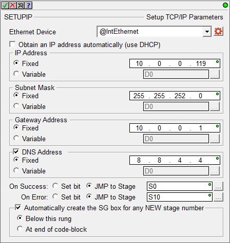
IP Address selects how the IP Address will be set. A copy of the current TCP/IP Address is stored in $IPAddress (DST18).
-
select Fixed to enter the IP Address as 4 separate decimal numbers, each one ranging from 0 to 255. Addresses 0.0.0.0, 127.0.0.1, and 255.255.255.255 are not allowed.
-
select Variable if the IP Address resides in the specified memory location. This can be any readable DWord numeric location. The Hexadecimal equivalent of each octet of the IP Address are stored in the bytes of the Variable Address location. For example: IP Address 192.168.100.006 in Hex would be C0.A8.64.06, and stored in the Variable Address location as 0xC0A86406. The 'IP Address' format selection in a Data View can be used to see the IP Address stored in the DWord location in the traditional dot-decimal notation (000.000.000.000).
Subnet Mask selects how the Subnet Mask will bet set. A copy of the current Subnet Mask is stored in $NetMask (DST19).
-
select Fixed to enter the Subnet Mask as 4 separate decimal numbers, each one ranging from 0 to 255. Addresses 0.0.0.0, and 255.255.255.255 are not allowed.
-
select Variable if the Subnet Mask resides in the specified memory location. This can be any readable DWord numeric location. The Hexadecimal equivalent of each octet of the Subnet Mask is stored in a byte of the Variable Address location, for example: Subnet Mask 255.255.252.000 in Hex would be FF.FF.FC.00, and stored in the Variable Address location as 0xFFFFFC00. The 'IP Address' format selection in a Data View can be used to see the IP Address stored in the DWord location in the traditional dot-decimal notation (000.000.000.000).
Gateway Address selects how the Gateway Address will be set. A copy of the current Gateway Address is stored in $Gateway (DST20).
-
select Fixed to enter the Gateway Address as 4 separate decimal numbers, each one ranging from 0 to 255. Addresses 127.0.0.1, and 255.255.255.255 are not allowed.
-
select Variable if the Gateway address resides in the specified memory location. This can be any readable DWord numeric location. The Hexadecimal equivalent of each octet of the Gateway Address is stored in a byte of the Variable Address location, for example: IP Address 192.168.100.1 in Hex would be C0.A8.64.06, and stored in the Variable Address location as 0xC0A86406. The 'IP Address' format selection in a Data View can be used to see the IP Address stored in the DWord location in the traditional dot-decimal notation (000.000.000.000).
Enable the DNS Server (Optional) to enter the TCP/IP Address of the first DNS server to contact for resolving the Name to an IP Address. The default value is 8.8.8.8 (decimal 34744072) which is Google's public DNS Server. Note: the option to set the DNS Server is only available when the on-board Ethernet port is selected.
- select Fixed Address to enter the DNS Server's IP Address as 4 separate decimal numbers, each one ranging from 0 to 255.
Addresses 127.0.0.1, and 255.255.255.255 are not allowed.
-
select Variable if the DNS Server's IP Address resides in the specified memory location. This can be any readable DWord numeric location. The Hexadecimal equivalent of each octet of the DNS Server's IP Address is stored in a byte of the Variable Address location, for example: IP Address 192.168.100.1 in Hex would be C0.A8.64.06, and stored in the Variable Address location as 0xC0A86406. The 'IP Address' format selection in a Data View can be used to see the IP Address stored in the DWord location in the traditional dot-decimal notation (000.000.000.000).
The On Success and On Error parameters specify what action to perform when this instruction completes. You do not have to use the same type of selection for both On Success and On Error.
If the Set Bit selection is used for either On Success or On Error, the specified BIT location will be SET OFF when the instruction is first enabled and will remain OFF until the instruction completes. Once complete, the appropriate Success or Error bit location ON. The specified Bit location is enabled with a SET (Latch) operation meaning that it will remain ON even if the input logic for the instruction goes OFF.
If the JMP to Stage selection is used for either On Success or On Error the target Stage must be in the same Program code-block as this instruction, you cannot specify a target Stage that exists in a different Program code-block. When the operation finishes, the target Stage will be enabled the same way as a standalone Jump to Stage (JMP) instruction would do it. The JMP to Stage option will only be available if this instruction is placed in a Program code-block.
On Success selects which of the following actions to perform if the operation is successful:
- Enable SET Bit then specify any writable bit location.
- Enable JMP to Stage then specify any
Stage number from S0 to S127 in the current Program code-block.
On Error selects which of
the following actions to perform if the operation is unsuccessful:
- Enable SET Bit then specify writable bit location.
- Enable JMP to Stage then specify any Stage number from S0 to S127 in the current Program code-block.
If either the On Success or On Error selections are set to JMP to Stage, Automatically create the SG box for any NEW stage number will be enabled which will automatically create any target stage that does not already exist.
- Below this rung will create the new target stage on a new rung following this instruction.
- At end of code-block will create the new target stage as the last rung of this Program.
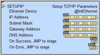
Status Display:
Assigning static IP Address information:
Using DHCP to assign IP Address information:
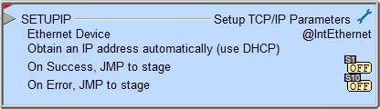
The red triangle in the upper left corner of the status display indicates this is a Fully Asynchronous instruction.
The gray triangle at the right end of the input leg indicates the input is edge-triggered, meaning this instruction will execute each time the input logic transitions from OFF to ON.
See Also:
SETUPIP - Setup TCP/IP Parameters
SETUPNOD - Setup Ethernet Node Parameters
Related Topics:
DNSLOOKUP - Name to IP Address
Example Using Stages: