Topic: DMD0071

SETUPNOD - Setup Ethernet Node Parameters
The Setup Ethernet Node Parameters (SETUPNOD) instruction is used to configure the Node Identifying parameters for the on-board Ethernet port of a Do-more controller or the Ethernet port of an ECOM100 module. For the on-board Ethernet port, the Do-more CPU keeps a copy of the current Node Number in $NodeNumber (DST17), the current System Name in SysName, and the current System Description in SysDesc. Any time this instruction is executed these three locations are updated.
Note: This instruction writes to the ROM in the CPU. As such, this instruction may take several seconds of time to complete. It is also important that this instruction NOT be executed more than is necessary because the ROM chip in the Do-more CPU has a limited number (~100K) of write cycles.
Parameters:
Note: Use the F9 key or click the 'three dot box' at the right edge of the parameter field to open the Default Element Selection Tool (the Element Picker or the Element Browser) or use the Down-Arrow key (Auto-Complete) on any parameter field to see a complete list of the memory locations that are valid for that parameter of the instruction.
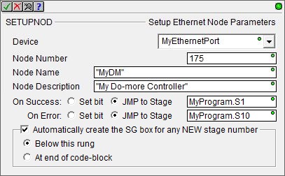
Device - selects the Ethernet device to configure.
no devices available - indicates that there are no Devices that can execute this instruction. The most likely cause is the CPU does not have an on-board Ethernet port or there is no ECOM100 module in the base.
create device - select this option to open the Device Configuration dialog of the System Configuration to create a new Ethernet device.
Node Number - the Node Number can be any positive 32-bit signed number from 0 to 2147483647 or any readable numeric location. The currently configured Node Number is stored in $NodeNumber (DST17).
Node Name - the Node Name can consist of 0 to 256 alphanumeric characters. The currently configured System Name is stored in SysName.
Node Description - the Node Description can consist of 0 to 256 alphanumeric characters. The currently configured System Description is stored in SysDesc.
The On Success and On Error parameters specify what action to perform when this instruction completes. You do not have to use the same type of selection for both On Success and On Error.
If the Set Bit selection is used for either On Success or On Error, the specified BIT location will be SET OFF when the instruction is first enabled and will remain OFF until the instruction completes. Once complete, the appropriate Success or Error bit location ON. The specified Bit location is enabled with a SET (Latch) operation meaning that it will remain ON even if the input logic for the instruction goes OFF.
If the JMP to Stage selection is used for either On Success or On Error the target Stage must be in the same Program code-block as this instruction, you cannot specify a target Stage that exists in a different Program code-block. When the operation finishes, the target Stage will be enabled the same way as a standalone Jump to Stage (JMP) instruction would do it. The JMP to Stage option will only be available if this instruction is placed in a Program code-block.
On Success selects which of the following actions to perform if the operation is successful:
- Enable SET Bit then specify any writable bit location.
- Enable JMP to Stage then specify any
Stage number from S0 to S127 in the current Program code-block.
On Error selects which of
the following actions to perform if the operation is unsuccessful:
- Enable SET Bit then specify writable bit location.
- Enable JMP to Stage then specify any Stage number from S0 to S127 in the current Program code-block.
If either the On Success or On Error selections are set to JMP to Stage, Automatically create the SG box for any NEW stage number will be enabled which will automatically create any target stage that does not already exist.
- Below this rung will create the new target stage on a new rung following this instruction.
- At end of code-block will create the new target stage as the last rung of this Program.
Status Display:
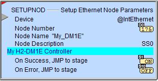
The red triangle in the upper left corner of the status display indicates this is a Fully Asynchronous instruction.
The gray triangle at the right end of the input leg indicates the input is edge-triggered, meaning this instruction will execute each time the input logic transitions from OFF to ON.
See Also:
SETUPNOD - Setup Ethernet Node Parameters
SETUPIP - Setup TCP/IP Parameters
Related Topics:
DNSLOOKUP - Name to IP Address
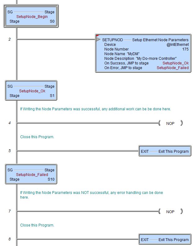
Example Using Stages:
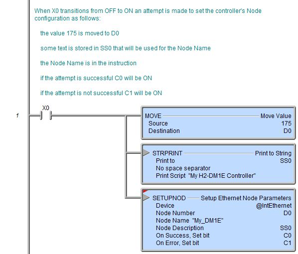
Rung Example: