Topic: DMD0263

CPU LEDs
Do-more CPUs have two-color LEDs that are used to visually provide operational status to the user. Each of the LEDs can be either RED, GREEN, or YELLOW. The LEDs can be ON continuously or blinking This gives the CPU many options for color combinations and blink patterns that can indicate different operational modes, and fault conditions, and provide diagnostic information and communication status.
In addition to the individual definition of each LED, there are times when the CPUs will use combinations of LED ON / OFF state and colors to convey status information. The following combinations use some or all of the LEDs:
ERR LED (BRX-DM1x & H2-DM1x) or STAT LED (T1H-DM1x) is blinking RED for (15 seconds) Do-more Designer can blink the ERR or STAT led for 15 seconds to verify that a communication link is targeting the correct CPU.
All of the LEDs are ON and the color of each LED is YELLOW indicates the boot loader has started running.
All of the LEDs are ON and the color of each LED is GREEN indicates the operating system has started running.
All of the LEDs are cycling through RED & GREEN, in a circular 'chase' pattern indicates the operating system is initializing.
The left-most LEDs are cycling through RED & GREEN, in a 'bouncing ball' pattern indicates the CPU is running only the boot loader and is NOT going to load and run the operating system. The most likely cause is having DIP switch #1 in the ON position.
All of the LEDs are ON, and the color of each LED is RED indicates that am unrecoverable hardware error has occurred. The CPU must be power-cycled to clear the error.
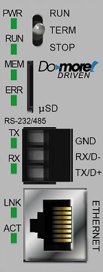
BRX-DM1 / BRX-DM1E LED Descriptions
|
|
|
OFF |
Base Power of OFF. |
|
|
GREEN - ON
|
Base Power is ON.
|
|
|
GREEN - BLINK
|
Ethernet
I/O Master is downloading configuration data to the Ethernet I/O Slaves. |
|
|
YELLOW |
Battery Voltage Low - click for instructions on
changing the battery. |
|
|
|
||
|
OFF |
||
|
GREEN |
CPU is in RUN mode. |
|
|
YELLOW |
CPU has one or more locations with Forced values. |
|
|
|
||
|
MEM |
OFF |
|
|
GREEN
|
A micro-SD card is installed in the slot and properly mounted and ready for access by the BRX CPU. |
|
|
YELLOW |
CPU is updating non-volatile memory (ROM). |
|
|
RED
|
A micro-SD card is in the slot but it is unmounted, it is not ready for access by the BRX CPU.
|
|
|
|
||
|
ERR |
OFF |
CPU is functioning normally. |
|
RED - ON
|
CPU has experienced one or more of the following conditions:
|
|
|
RED- BLINK
|
Blink To Identify the CPU from Edit Link dialog.
|
|
|
|
||
|
RX / D- |
GREEN |
Serial port is receiving data, OFF means no data being received. |
|
GREEN |
Serial port is transmitting data, OFF means no data being sent. |
|
|
LNK |
GREEN |
Ethernet Link is Good, OFF typically means the cable is not properly connected. |
|
ACT |
GREEN |
Ethernet is sending or receiving data, OFF means no data being sent or received. |
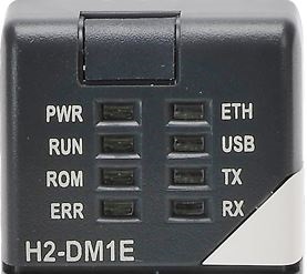
H2-DM1 / H2-DM1E LED Descriptions
|
|
|
PWR |
OFF |
|
|
GREEN - ON
|
DL205 Base Power is ON.
|
|
|
GREEN - BLINK
|
Ethernet
I/O Master is downloading configuration data to the Ethernet I/O Slaves. |
|
|
YELLOW |
Battery Voltage Low - click for instructions on
changing the battery. |
|
|
|
||
|
RUN |
OFF |
CPU is in STOP (Program) mode. |
|
GREEN |
CPU is in RUN mode. |
|
|
YELLOW |
CPU has one or more locations with Forced values. |
|
|
|
||
|
ROM |
OFF |
Non-volatile memory (ROM) is up to date. |
|
YELLOW |
CPU is updating non-volatile memory (ROM). |
|
|
|
||
|
ERR |
OFF |
CPU is functioning normally. |
|
RED |
CPU has experienced one or more of the following conditions:
|
|
|
|
||
|
ETH |
GREEN |
Ethernet Link is Good. |
|
YELLOW |
Ethernet Activity. |
|
|
RED |
Ethernet is transmitting data. |
|
|
|
||
|
GREEN |
USB is receiving data. |
|
|
YELLOW |
USB is transmitting data. |
|
|
|
||
|
TX |
GREEN |
Serial port is transmitting data, OFF means no data being sent. |
|
RX |
GREEN |
Serial port is receiving data, OFF means no data being received. |
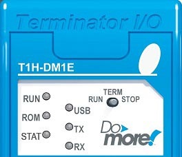
T1H-DM1 / T1H-DM1E LED Descriptions
|
|
|
RUN |
OFF |
CPU is in STOP (Program) mode. |
|
YELLOW |
CPU is in RUN mode.
|
|
|
GREEN |
CPU has one or more locations with Forced values. |
|
|
|
||
|
ROM |
OFF |
Non-volatile memory (ROM) is up to date. |
|
YELLOW |
CPU is updating non-volatile memory (ROM). |
|
|
|
||
|
STAT |
GREEN |
CPU is functioning normally. |
|
YELLOW |
Battery Voltage Low - click for instructions on changing the battery. |
|
|
RED |
CPU has experienced one of the following conditions:
|
|
|
|
|
|
|
USB |
GREEN |
USB is receiving data. |
|
YELLOW |
USB is transmitting data. |
|
|
|
||
|
TX |
GREEN |
Serial port is transmitting data, OFF means no data being sent. |
|
RX |
GREEN |
Serial port is receiving data, OFF means no data being received. |
See Also:
System
Setup and Maintenance Overview
Configuring
the Hardware Watchdog Timer
Mode Switch Position
Definitions
Configuring the On-board Ethernet Port