Topic: DMD0261

Battery Backup
All Do-more CPUs have a replaceable battery and an on-board capacitor that work in concert to maintain the contents of the retentive memory any time the main power to the CPU is lost. If the battery and the on-board capacitor voltages become too low the contents of retentive memory will be lost if the main power to the system goes off. Any time that the CPU detects that the battery voltage is too low, and needs to be replaced, the PWR LED will be YELLOW instead of it's normal GREEN color and the system-defined Bit location $BatteryLow (ST149) will be ON.
Contents of Retentive Memory
Values of the following data items are maintained by the battery and on-board capacitor through a power cycle. If the Battery voltage gets too low and the on-board capacitor is drained the values for these items will reset to 0 or to an appropriate initial value.
-
The current Date & Time.
-
The state of the Mode Switch.
-
The default configuration for a Do-more CPU has all of the predefined memory blocks marked as retentive except those blocks memory that are used for I/O memory (X, Y, WX, WY, DLX and DLY) . When the user creates additional memory block, Programs, Tasks, etc. there is an option to mark these elements a retentive, and they will be battery backed as well.
-
The Do-more CPU also keeps a copy of the last known good I/O Configuration data stored in the battery-backed memory. While the system is powered down, if an I/O module is removed, or an I/O module is added, or an existing I/O module is replaced with a different one, the collection of I/O modules will not match the collection that is in the battery-backed memory when the system is powered back on. The Do-more CPU will detect that the I/O modules in a PLC system changed during the power-cycle and will turn ON the System Information bit $InstIOChanged (ST134) - Module Configuration Changed at Power up.
Note: if the $BatteryLow (ST149) and the $InstIOChanged (ST134) are ON at the same time the Do-more CPU will power up in PROGRAM mode because the last known good copy of the I/O Configuration will NOT be present when the aforementioned comparison is done.
Warning! If you absolutely need for the CPU to go into RUN mode with the CPU in this low battery condition then you will need to visually determine that the currently detected I/O Configuration is valid for the use by the project in the CPU, then use either the Mode Switch on the front of the CPU or Do-more Designer's PLC Mode utility to manually place the CPU in RUN mode.
Operating Without the Battery
Under normal operating conditions, if the battery and the on-board capacitor are both depleted the CPU will NOT power up in RUN mode because the above-mentioned retentive elements will have reverted to their initial (unconfigured) state. If you need the CPU to power up in RUN mode without the battery and on-board capacitor maintaining the retentive memory, it can be made to so do as follows:
-
Update the DM1 / DM1E firmware to v1.3.1 or later.
-
Set the Mode Switch to the RUN position.
-
Change the I/O Configuration Mode to Manual.
If the system powers up with the above settings made, AND the I/O Configuration that is detected by the Do-more CPU exactly matches the I/O Configuration that is stored in the ROM copy of the System Configuration then the CPU will attempt to go into RUN mode.
Changing the Battery
Make sure to have a current copy of the Do-more Designer project saved to Disk before performing this operation.
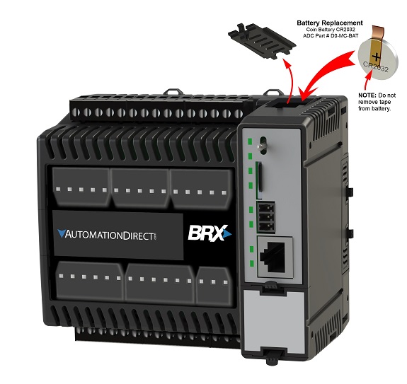
The battery is a standard CR2032 coin cell battery, (Automationdirect part # D0-MC-BAT). The battery itself has an expected shelf life of 5 years, a lifespan of 3 years if installed.
Note: the Do-more CPUs have an on-board capacitor that will maintain the retentive memory contents while the battery is being replaced. Even though this capacitor has a 2 hour runtime - which should be more than enough time to replace the battery - DO NOT begin this operation unless you have the replacement battery in hand.
BRX-DM1 / BRX-DM1E
Power down the system.
Remove the top cover plate, using a small screwdriver.
Remove the battery from it's holder that is located on the left-side of the CPU's main board by pulling the tape attached to the battery. Take note of how the battery is aligned in the holder so that the new battery can be put back in the same orientation. Failure to replace the battery properly can result in damage to the CPU.
Note: do not remove the tape from the new battery.
Insert the new battery into the battery holder, making sure the alignment is correct and the piece of tape used to remove the battery comes straight out the top of the battery holder.
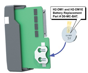
Power down the system containing the CPU and remove the CPU from the base.
Remove the battery from it's holder that is located on the back of the CPU's main board, in the lower right corner. The battery is removed by pulling the tape attached to the battery. Take note of how the battery is aligned in the holder so that the new battery can be put back in the same orientation. Failure to replace the battery properly can result in damage to the CPU.
Note: do not remove the tape from the new battery.
Insert the new battery into the battery holder, making sure the alignment is correct and that the piece of tape used to remove the battery comes straight out the back of the battery holder.
Place the CPU back in the CPU slot of the 205 base.
Power up the system.
Verify that the PWR LED is now GREEN instead of YELLOW and the system-defined location $BatteryLow (ST149) is OFF.
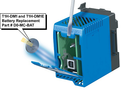
T1H-DM1 / T1H-DM1E
Power down the system.
Remove the front cover plate, using a small screwdriver.
Remove the battery from it's holder that is located on the bottom of the CPU's left-side main board. The battery is removed by pulling the tape attached to the battery. Take note of how the battery is aligned in the holder so that the new battery can be put back in the same orientation. Failure to replace the battery properly can result in damage to the CPU.
Note: do not remove the tape from the new battery.
Insert the new battery into the battery holder, making sure the alignment is correct and that the piece of tape used to remove the battery comes straight out the front of the battery holder.
Replace the front cover.
Power up the system.
Verify that the PWR LED is now GREEN instead of YELLOW and the system-defined location $BatteryLow (ST149) is OFF.
See Also:
System
Setup and Maintenance Overview
Changing the On-board Battery
Configuring
the Hardware Watchdog Timer
Mode Switch Position
Definitions
Configuring the On-board Ethernet Port