Topic: DMD0264

CPU Mode Switch
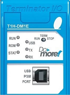
The Mode switch on the front of the DM1 / DM1E CPUs is used to manually set the operational mode of the CPU. The Mode switch is located in the top right corner of the front bezel. The mode switch has the following three positions:
-
RUN - put the CPU into RUN mode - assuming there are no issues that prevent it from happening, like errors in the project currently loaded in the CPU, or a problem with the hardware.
-
TERM - (Terminal) - placing the switch in this position allows the Do-more Designer programming software to set the CPU's mode using the Set PLC Mode utility.
-
STOP - put the CPU into Stop (Program) mode which stops running the currently loaded project.
|
BRX-DM1 /BRX-DM1E 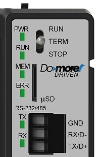
|
|
T1H-DM1 / T1H-DM1E
|

How the Mode Switch Affects Power-Up State
When power is applied to the system, the CPU will go through it's power-up sequence then either stay in Program mode if the mode switch is in the STOP position, or attempt to go to Run mode if the mode switch is in the RUN position.
If the mode switch is in the TERM position, the CPU will return to the last operational mode before power was lost. For example, if the CPU was in Run mode when power was lost, when power is restored and the mode switch is in the TERM position, the CPU will attempt to return to Run mode.
There is a distinction between powering up in Run mode and performing a Program -to- Run mode change. the System Bit $PgmModeRestart (ST15) will indicate whether the last change to Run mode was from a power-on condition or a mode change.
$PgmModeRestart (ST15) will be ON after a Program mode -to- Run mode transition. Non-retentive memory has been cleared, retentive memory has not been changed, but the state information of all Programs (including their Stage bits) and Tasks have been reset even if the Program or Task has been configured as retentive.
$PgmModeRestart (ST15) will be OFF in Run mode after a power-up, or a restart after a Watchdog Timer event, or after a REBOOT instruction is executed. Non-retentive memory has been cleared, retentive memory has been preserved. The state information for Programs and Tasks marked as retentive has been preserved, those NOT marked as retentive has been cleared.
Note: the Difference Between Two Date / Times (DTDIFF) instruction with SDT1 ($SysShutdown) and SDT2 ($SysStartup) can be used to determine how long a CPU has NOT been in Run mode. The result of this calculation can be used to help decide what (if anything) needs to be manually reset based on the amount of time the PLC was not in control of the machine or process.
See the Current Mode Switch Position in Do-more Designer
The current position of the mode switch can be seen in the Do-more Designer programming software in the Current PLC Settings group of the Set PLC Mode dialog.
The current mode can also been seen on the Status bar.
The current PLC mode (not the position of the mode switch) can be seen programmatically in the ON / OFF status of $TermRunMode (ST16).

The status bar group shows the three mode position options, with the current position in Blue, This is the image that will be displayed when the mode position is in the TERM position:
See Also:
System
Setup and Maintenance Overview
Configuring
the Hardware Watchdog Timer
Mode Switch Position Definitions
Configuring the On-board Ethernet Port