Topic: DMD0210

Using the Data View
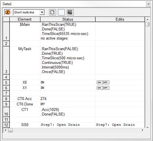
The Data View is used to monitor the status of, and optionally change the values of selected memory locations in the Do-more CPU. Multiple Data Views can be open at the same time, each viewing the same or different memory locations, in the same or a different format (Native, Binary, Octal, BCD/ Hex, etc.).
The Data View dialog is a Dockable![]() A Dockable window is one that can be connected to the sides, top, or bottom of another window.
Docking is done by clicking the mouse in the colored portion of the top bar of the window and dragging it toward the edge of the contain window. As it approaches the containing window, a reverse video block will appear, showing how the docked window will appear in its docked form.and Floatable
A Dockable window is one that can be connected to the sides, top, or bottom of another window.
Docking is done by clicking the mouse in the colored portion of the top bar of the window and dragging it toward the edge of the contain window. As it approaches the containing window, a reverse video block will appear, showing how the docked window will appear in its docked form.and Floatable![]() This window can "float" on the screen and remain functional while being unconnected to an edge of a containing window.
Floating a window is done by clicking the mouse in the colored portion of the top of the window and dragging it away from the edge, As the window is dragged away, a reverse video block will appear, showing how the window will appear in it's floating form.window. Double-clicking on the title bar will toggle between the Docked and Floating states.
This window can "float" on the screen and remain functional while being unconnected to an edge of a containing window.
Floating a window is done by clicking the mouse in the colored portion of the top of the window and dragging it away from the edge, As the window is dragged away, a reverse video block will appear, showing how the window will appear in it's floating form.window. Double-clicking on the title bar will toggle between the Docked and Floating states.
To create a new Data View select the Debug -> Data View -> New menu option, or press the Ctrl+Shft+F3 keys.
To open an existing Data View select the Debug -> Data View -> Open menu option. The File Open dialog will appear, allowing the user to navigate to the saved data view file.
To save the current Data View, select the Debug -> Data View -> Save menu option. If the Data View has previously been saved, then the current contents of the Data View will be written to the previously specified file. If the Data View has not been previously saved, the SaveAs dialog will appear, allowing the user to specify a file name.
The Data View Dialog
The following is a quick discussion of the toolbar buttons found at the top of the Data View dialog, from left to right:
Click the Edit
Mode button (right-click -> Toggle Edit Mode) to
enable the write operation for elements in the Data View that are read/write.
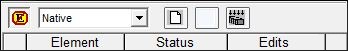
The Display
Format drop-down will contain a list of display
formats that are appropriate for the selected element. The default display
format for non-structure elements is "Native",
which means the element's value will be displayed in the proper format
for it's native data type. This will normally be the correct selection
for numeric values, and should only be changed to specifically display
the value in a particular format. For example, displaying unsigned values
as Hexadecimal or Binary is sometimes appropriate when the bits of that
value represent flags or status bits.
The optional display formats available for bit and numeric fields are:
Binary, Octal , BCD / Hex, Timer, Seconds Time, Date Field, Time Field,
1970 Epoch, IP Address.
Structures are a special case because they have multiple fields with differing data types. Displaying structures in the Data View will take multiple rows, so there are four different displays formats specifically for structure that take this into account: They are: "critical multi-line","critical single line", "useful multi-line", and "useful single line". These display formats have varying amounts of data and are oriented for tall / thin displays or short / wide displays. The default display format for structures is "short multi-line".
Strings too are a special case in that there are some purpose-built
display formats that aid in debugging string manipulation operations.
Refer to the following example where the String element SS0 contains "Step
7: Open Drain Valve". This table lists the 7 display formats and
shows how the contents of SS0 will be displayed in each.
The three buttons to the right of the format
field are used to manage the contents of the Edits columns as follows:
Click the Clear Edits button to remove all of the values from the Edits column.
Click the Write Current Edit button to write the value in the Edits column for the currently selected element only. The following message box is displayed:
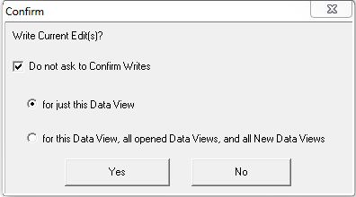
Check Do not ask to Confirm Writes to disable this Confirm Writes message on future Write Current Edit operations. The following two options determine the extent of disabling the Conform Writes message:
- just for this Data View will only disable Confirm Writes for this Data View, all other Data Views will control their own Confirm Writes operations.
- for this Data View, all open Data View, and All New Data Views will disable Confirm Writes for this Data View, any Data Views that are already open, and any newly created Data View. Selecting this option disables the Confirm Writes selection in the Safety section of the Data View Global Options.
Click the Write All Edits button to write all of the values in the Edits column to the CPU. A confirmation dialog will be displayed because the process of writing multiple edits can take multiple CPU scans which means that the all of values might NOT end up in the PLC on the same PLC scan.
Enable the In the future, always perform multiple writes without confirmation to write the multiple edits without having this confirmation dialog pop up each time.
Right-click in the Data View and Select Copy Status to Edit and, for the selected Element or selected Range of Elements, this will copy the Status value to the corresponding Edit field. If no Element or Range of Element has been selected the following dialog will be displayed:
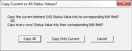
Copy All will copy the Status values of All the Elements to their corresponding Edit field.
Copy Only Current will copy the Status value for the selected Element to its corresponding Edit field.
Cancel will close the dialog without copying the Status value to the Edit field.
The remaining portion of the Data View is a grid that has three columns, as follows:
Element contains the memory elements to monitor.
Status displays the current value of the element, using the selected display format.
Edits is only visible if Edit Mode is enabled - is where the user enters new values for the memory element.
Customizing the Data View Display
The look and functionality of the Data Views can be customized by the selections on the Data View tab of the View -> Options menu.
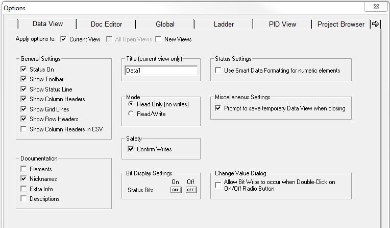
The 'Apply Options to' selections at the top specify which Data Views the changes to the options will be applied to.
Current View changes apply only to the currently selected Data View.
All Open Views changes apply to all of the currently open Data Views.
New Views changes do not apply to the currently selected Data Views, only to Data Views that are opened from this point forward.
The General Settings group controls
the look of the grid.
When Status On is enabled, status updates will occur.
When Show Toolbar is enabled, the toolbar will be displayed at the top of the dialog.
When Show Status Line is enabled, the status bar at the bottom of the dialog will be displayed.
When Show Column Headers is enabled, the "Elements", "Status", and "Edits" column headers will be displayed.
When Show Grid Lines is enabled, the horizontal and vertical grid lines will be displayed.
When Show Row Headers is enabled, the row numbers will be displayed.
When Show Column Headers in CSV is enabled, the "Elements", "Status", and "Edits" column headers will be exported along with the Data View contents when a Data View-> Export operation is performed.
The Documentation group enables / disables the element documentation display
in the element column.
If Elements is enabled, the element name will be displayed.
If Nicknames is enabled, for elements that have nicknames, the nickname will be displayed. Note: either Elements or Nicknames or both must be enabled.
If Extra Info is enabled, the element's Extra Info (if present) will be displayed.
If Descriptions is enabled, the element's Description (if present) will be displayed.
The Title (current view only) allows the user to specify a 16 character name for the currently selected view. By default, Data Views are named "Data" plus a sequentially assigned number.
The Mode group specifies whether
the Data View can write new values for CPU elements.
-
Read Only (no writes) disables the Data View's ability to write to the CPU.
-
Read / Write (the default) enables the Data View's ability to write to the CPU.
The Safety selection specifies
whether a write operation will display a confirmation before the operation
is performed.
Click on the "Confirm Writes" check box to enable the confirmation dialog before any write operations are performed
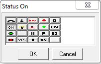
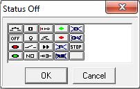
The Bit Display Settings group
allows the user to select what is displayed in the Status column for bit
elements.
Click on the "On" button to display the following dialog that contains additional icons that can be displayed for the ON status of a bit element.
Click on the "Off" button to display the following dialog that contains additional icons that can be displayed for the OFF status of a bit element.
The Status Settings selection specifies display options while Status is ON.
Click on the "Use Smart Formatting for Numeric Elements" check box to have the Data View automatically display certain types of values in a format that is more human-readable.
For example, when displaying a TCP/IP Address, the 'smart' format will show the value in the traditional dotted decimal format (192.168.100.123) rather than the hexadecimal value in the DWord location (0xC0A8647B).
Miscellaneous Settings
When closing a Data View, if it has not been previously saved you will be Prompted to save temporary the Data View before it is closed.
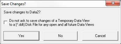
Checking the box will disable this option and you will no longer be prompted to save temporary Data Views.
The Change Value Dialog selection has options for the Change Value dialog.
Click on the "Allow Bit Write to Occur when Double-Click on Radio Button" check box to allow the Change Value dialog to process a Write operation with a double-click instead of requiring that you click on the 'Write to {PLC' button.
Click the OK button to save the changes to the Options.
Click the Cancel button to discard any changes made to the Options.
Entering Elements
Entering elements in a Data View is quite easy, simply place the cursor in a cell in the Element column and type in the name of the memory element (or it's nickname if it has one) then press the enter key. memory elements can also be entered by selecting them from the Element Browser (F9), or using the down-arrow (auto-complete).
Editing an item in a Data View is done by placing the cursor on the item to be edited and press <F2>, or double-clicking on the item to be edited.
Deleting an item from a Data View is done by placing the cursor on the item to be deleted and pressing the delete key. To delete a range of items, select the range and press the delete key. To select a range of items, place the cursor on the first item to be selected. Hold down the <shift> key and press the up or down arrows, or click with the mouse and drag the cursor to select the desired range of items. Pressing the delete key a second time will move the contents of the rows below the deleted element up one row.
Using the cut / copy / paste operations to add / remove items from / to data views is done by selecting the items to be cut, copied, or pasted, then selecting the appropriate option from the edit menu. The cut option will remove the selected items from the current view and place them into the cut buffer. The copy option will leave the selected items in the current view AND place them into the cut buffer. The paste option will copy the items from the cut buffer into the current view.
Adding Successive Elements
The auto-increment option is a quick way to add a range of elements to a Data View. To use this feature, add the first element of the range to the Data View. Then place the cursor on the first element of the range and press Ctrl+Enter (or right-click on the item with the mouse and choose Increment). The next memory element in that range will be added to the Data View.
Structures in the CPU are handled as a special case of the increment option because Structures have multiple fields. The auto-increment operation changes based on what has been selected:
If the structure
element itself is being incremented:
Ctrl+Enter - (Increment) adds the next structure to the Data View. For example, if Timer structure T0 is selected, Ctrl+Enter will add the Timer structure for T1 to the Data View.
Ctrl+Shft+Enter - (Expand Structure) adds all of the elements of the structure to the Data View. For example, if Timer structure T0 is selected, Ctrl+Shift+Enter will add all of the structure fields from Timer Structure T0 to the Data View.
If a single
field of a structure is being incremented:
Ctrl+Enter - (Increment) adds the same field of the next structure to the Data View, For example. if the field T0.Acc is selected, Ctrl+Enter will add T1.Acc to the Data View.
Ctrl+Shift+Enter - (Next Field) adds the next field (this could be the next field in the same structure or the first field of the next structure) to the Data View. For example, if the field T0.Acc is selected, Ctrl+Shift+Enter will add T0.Done to the Data View. The next Ctrl+Shift+Enter will add T0.Zero to the Data View.
Sorting the Elements
The list of elements in a Data View can be sorted alphabetically by the Element name.
Use Ctrl + Shft + A (or right-click in the Data View and select Sort-> Ascending) to sort the list of Elements into ascending order.
Use Ctrl + Shft + D (or right-click in the Data View and select Sort-> Descending) to sort the list of Elements into descending order.
Note: Any blanks lines in the Data View will be removed as part of the sort operation.
Using Cast Operators to Control How Values are Displayed in a Data View
Casting is a ”C"-programming language term that means "to change the type of" a variable. Do-more Designer uses the colon ":" character to perform casting operations. The most common situations where casting is used are mapping operations like bit-picks or packing bits into Bytes, Words, or DWords. Except for 'Bit-of-Word' and Mapping Bit Ranges to Bytes, Words, or DWords operations, casting elements from one type to another is not needed. For detailed information on using Cast operations in Do-more Designer refer to the help topic on Casting.
Changing the Update Interval for all Data Views
There are times when the ability to change the default update rate of the various Views in the Do-more Designer software is needed. By default, Do-more Designer will generate communication requests at a rather high rate in an effort to present the most current status values for the on-screen elements. But on computers that are CPU-speed-challenged or memory-challenged, maintaining this update rate at the expense of allowing CPU time for other processing can be a problem. To address this need, Do-more Designer uses two entries in the [SETUP] group of DmDesigner.Ini, named ProgViewInterval & DataViewInterval, to govern the rate at which the Views will update the values of the elements they contain.
ProgrViewInterval applies to Ladder Views, Debug Views, the Module Browser, Data Views, Device Views, PID Overview, etc.. Its value is the frequency (in milliseconds) that status communication requests occur for those views. The default for these views is 25ms. If the entry does not exist, or is commented out (like in the example below), the frequency will be the 25ms default. This value can have it be as small (for a fast update), or as large (for a slow update) as desired. A value of 0 means "as fast as possible"
The Data View has a separate entry, called DataViewInterval, in the same group, Its value is the frequency (in milliseconds) that status communication requests occur only for Data Views. The default value is 75ms.
If both ProgViewInterval & DataViewInterval exist in DmDesigner.Ini, ProgViewInterval will supersede DataViewInterval ONLY if it is SLOWER (i.e. a higher number). If only the ProgViewInternal exists, any Data View will use the slower of that value or the value or 75 (the default for Data Views).
The default condition for both of these entries is that they are both commented out (as shown below), meaning that all of the views in Do-more Designer will operate at an update frequency of 25ms, and on most modern computers with sufficient RAM the default intervals should not cause any issues.
[SETUP]
;ProgViewInterval=25
;DataViewInterval=75
To engage one of these settings, remove the semicolon from the entry and change the update interval to the millisecond value desired.
Note: because Do-more Designer only reads the entries from DmDesigner.Ini when the software is first started, Do-more Designer will need to be closed, then re-opened to put the changes into effect.
Exporting Data View Elements
The Elements in a Data View can be exported for use in other operations in Do-more Designer as follows:
To Export All of the Contents of a Data View in CSV format:
Right-click with the mouse on the Data View and select Export-> All from the pop-up menu.
The Save As dialog will appear, allowing the programmer to specify a file name.
Each Element in the Data View and its associated Status value will be exported to the specified file, one "Element,Status Value" pair per line.
To Export only Some of the Contents of a Data View in CSV format:
Click and drag with the mouse (or use the shift + arrow keys) to select the entries in the Data View to export
Right-click with the mouse on the Data View and select Export-> Selection from the pop-up menu.
The Save As dialog will appear, allowing the programmer to specify a file name.
Each of the selected Elements and its associated Status value will be exported to the specified file, one "Element,Status Value" pair per line.
To Open a new Trend View with All of the contents of a Data View:
Right-click with the mouse on the Data View and select Trend All from the pop-up menu to send all of the Elements in the Data View to the new Trend View.
To Open a new Trend View with only Some of the contents of a Data View:
Left-click and drag with the mouse (or use the shift + arrow keys) to select the entries in the Data View to send to the Trend View.
Right-click with the mouse on the Data View and select Trend Element / Selection from the pop-up menu to send only the previously selected elements in the Data View to the Trend View.
See Also:
Using
the Trend View to Monitor to Graph Values Over Time
Using the Data View to Monitor and Change Data Values
Using Memory View to Monitor and Change Memory Values
Using Memory Image Manager for Retentive Memory