Topic: DMD0266

On-board DIP Switches
The Do-more CPUs have a block of 8 DIP switches that are used to perform various debug and recovery operations. The DIP switch settings are only read when the system is first powered up so any changes made to them will require a power-cycle to take effect.
BRX-DM1 / BRX-DM1E
The DIP switch block is located on the right side CPU's main board under the removable cover on the top of the CPU.
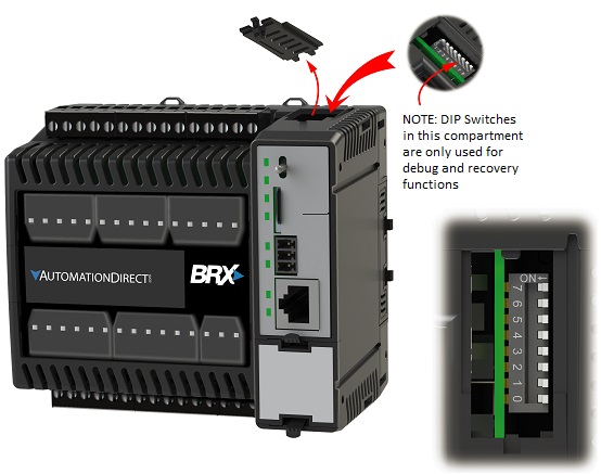
The DIP switch block is located on the front side of the CPU's main board and is only accessible when the CPU is NOT installed in the base. Accessing the DIP switches requires that the base containing the CPU be powered down and the CPU must be removed from the base. The DIP switches can then be changed as required, the CPU can then be reinstalled in the base and the system powered back up.

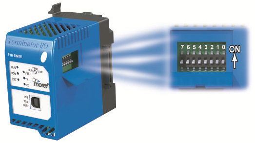
T1H-DM1 / T1H-DM1E
The DIP switch block is located under a cover on the CPU's main board and is only accessible when the CPU is NOT connected to its I/O modules. Accessing the DIP switches requires that the system be powered down and the CPU disconnected from the I/O modules. The DIP switches can be changed as required, then reconnected to the I/O modules and the system powered back up.
Description for Individual DIP Switches
| Number | Name | Description | Additional Notes |
|
0 |
Load Oldest OS |
OFF (default) - Load the newest copy of the operating system.
ON - Load the oldest copy of the operating system.
|
If a firmware update has been applied to a CPU, the previous version of the firmware will be retained. This switch allows the user to load the previously stored version. |
| 1 |
OFF (default) - on power-up, the CPU will load the operating system and power up normally.
ON - on power-up, the CPU will NOT load the operating system, it will remain in the boot loader.
|
When the CPU is running in the boot loader the PWR, RUN, ROM, and ERR LEDs will be flashing in a 'bouncing ball' pattern. |
|
| 2 |
Disable Hardware Watchdog |
OFF (default) - the Force Watchdog Error (WATCHDOG) instruction and Debug Mode can generate a Watchdog timeout.
ON - the Force Watchdog Error (WATCHDOG) instruction and Debug Mode CAN NOT generate a hardware watchdog timeout.
|
The Hardware watchdog is always enabled, so this switch only affects the ability of Do-more Designer or the project to generate a hardware watchdog timeout event at runtime. |
| 3 |
OFF (default) - Do-more Designer can update the CPU's firmware and / or the gate array. ON - Do-more Designer CAN NOT update the CPU's firmware and / or the gate array.
|
||
| 4 |
Force On-board Serial Port to Programming Mode
|
OFF (default) - the on board serial port can be configured through the System Configuration.
ON - forces the on-board serial port into Do-more Programming mode using the default configuration (115200 baud, No Parity, 8 Data Bits, 1 Stop Bit, No Hardware Flow Control, Unit Address 1). |
Because the BRX CPU does not have a dedicated programming port, this DIP switch allows the user to temporarily override the port setup selections in the System Configuration for the on-board serial port and gain access to the CPU with Do-more Designer. Once the DIP switch is set OFF the port setup selections in the System Configuration will again be used when the PLC powers up.
Note: If the on-board Serial port has been configured as a Modbus/RTU Client or for Program Control, the client device for those selections will not be created when the project loads and you will see an Invalid Instruction Warning for any instruction that uses one of those client devices. This warning will prevent the CPU from powering up in RUN mode. Once the DIP switch is returned to the OFF position, on the next power cycle the client devices will be automatically created as before, but you will need to manually put the CPU back into RUN mode.
|
| 5 |
Reserved |
||
| 6 |
Reserved |
||
| 7 |
OFF (default) - clear all of the user data and reset the Ethernet Network settings to their factory default values.
ON - only reset the Ethernet Network settings (TCP/IP Address, Subnet Mask, Gateway Address) to their factory default values.
|
Must be used in conjunction with switch #1, refer to the Clear All User Data vs Clear only the Ethernet Network Settings sections below. |
DIP Switch / Mode Switch Combinations
Do-more CPUs make use of combinations of DIP switch settings and the Mode switch on the front of the CPU to perform two reset functions. These reset functions can only be performed when the CPU is in the boot loader. The following sequences describe the steps necessary to perform reset operations. This combination of DIP switch settings and mode switch manipulation is purposely complex to prevent these reset operations from being accidentally executed.
Clear only the Ethernet Network Settings
This reset function will clear ONLY the Network settings, which consists of the Module ID, Module Name, Module Description, IP Address, Subnet Mask and Gateway Address.
Begin by powering down the system.
Remove the CPU (if needed to gain access to the DIP switches) from the base and record the location of the DIP switches so they can be set back to their original position after the manual reset is finished.
Set ONLY DIP switches #1 and #7 ON to perform the Clear Only the Network Settings operation, make sure all other DIP switches are OFF.
Reinstall the CPU in the base (if it was removed).
Set the mode switch to TERM (the center location).
Power up the system.
At this point the left bank of 4 LEDs should be blinking the 'stay in the boot loader sequence', that is, they should be blinking in sequence, from top to bottom then back to the top, alternating between red and green.
Move the mode switch to RUN.
Move the mode switch to TERM.
Move the mode switch to RUN.
Move the mode switch to TERM.
Move the mode switch to TERM - the LEFT bank of 4 LEDs should now be ON
Note: if you want to terminate the reset at this point you can do so by moving switch to RUN instead of STOP or powering down the controller.
Move the mode switch to STOP - the RIGHT bank of 4 LEDs should now be ON
Note: if you want to terminate the manual reset at this point you can only do so by powering down the controller.
Move the mode switch to TERM - left bank LEDs begin flashing the power up sequence, and the ROM led should briefly be ON indicating that the data in the ROM is being rewritten. The LEDs will then begin flashing the 'staying in boot loader' sequence indicating the reset is complete.
Power down the system.
Remove the CPU (if needed to gain access to the DIP switches) from the base and return the DIP switches to their original positions.
Reinstall the CPU in the base (if it was removed).
Set the mode switch to its original position.
Clear All
This reset function will clear everything from the CPU, this includes the Network as described above, and the System Configuration, Memory Configuration, all control logic, all Documentation, and all of the User Accounts and Passwords.
Begin by powering down the system.
Remove the CPU (if needed to gain access to the DIP switches) from the base and record the location of the DIP switches so they can be set back to their original position after the manual reset is finished.
Next set all eight of the DIP switches ON to perform the Clear All operation.
Reinstall the CPU in the base (if it was removed).
Set the mode switch to TERM (the center location).
Power up the system.
At this point the left bank of 4 LEDs should be blinking the 'stay in the boot loader sequence', that is, they should be blinking in sequence, from top to bottom then back to the top, alternating between red and green.
Move the mode switch to RUN.
Move the mode switch to TERM.
Move the mode switch to RUN.
Move the mode switch to TERM.
Move the mode switch to STOP.
Move the mode switch to TERM - the LEFT bank of 4 LEDs should now be ON
Note: if you want to terminate the reset at this point you can do so by moving switch to RUN instead of STOP or powering down the controller.
Move the mode switch to STOP - the RIGHT bank of 4 LEDs should now be ON
Note: if you want to terminate the manual reset at this point you can only do so by powering down the controller.
Move the mode switch to TERM - left bank LEDs begin flashing the power up sequence, and the ROM led should briefly be ON indicating that the data in the ROM is being rewritten. The LEDs will then begin flashing the 'staying in boot loader' sequence indicating the reset is complete.
Power down the system.
Remove the CPU (if needed to gain access to the DIP switches) from the base and return the DIP switches to their original positions.
Reinstall the CPU in the base (if it was removed).
Set the mode switch to its original position.
See Also:
Configuring the Hardware Watchdog Timer
Mode Switch Position Definitions
Configuring the On-board Ethernet Port