Topic: DMD0437

Module Configuration for BX-SERIO using DMX512 Protocol
A DMX512 network consists of a single DMX512 Controller and one or more DMX512 Slave devices connected via a multi-drop bus topology. A DMX512 network can be no more than 1,200 meters (3,900 ft) long, with not more than 32 unit loads on a single bus. DMX512 electrical specifications are identical to those of the EIA-485-A standard. DMX512 data is transmitted over a differential pair using EIA-485 voltage levels. Network wiring consists of a shielded twisted pair, with a characteristic impedance of 120 Ohms, with a termination resistor at the end of the cable furthest from the Controller to absorb signal reflections.
Note: DMX512 protocol does not include automatic error checking and correction, and so is not an appropriate control for hazardous applications such as pyrotechnics or movement of theatrical rigging. False triggering may be caused by electromagnetic interference, static electricity discharges, improper cable termination, excessively long cables, or poor quality cables.
DMX512 Protocol Selection on BX-SERIO
The final two Protocol selections for ports on the BX-SERIO module will put the serial port into DMX512 mode - either as a Controller or a Slave - which allows the SERIO module to connect the Do-more CPU to a DMX512 network. When either DMX512 option is selected, the Port Type is fixed at RS-485 and the port settings are fixed at 250k baud, one start bit, eight data bits, two stop bits and no parity; this port configuration cannot be changed.
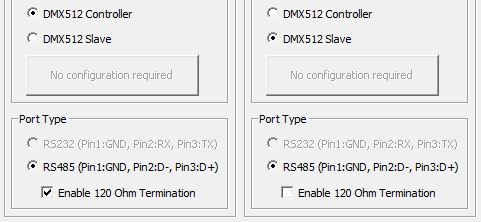
The Port Type is fixed at RS-485. Enable the 120 Ohm Termination if the serial port is configured as a Controller, or it if the last Slave on the DMX network; leave the termination unselected for any intermediate Slaves.
DMX512 Structure Members
Each BX-SERIO port that has been configured as either a DMX512 Controller or DMX512 Slave will have an associated structure automatically created . The structure will be named the same as the aforementioned memory block, the default names are $DMXA / $DMXB / $DMXC / $DMXD. The structure fields can be used in the ladder logic program. The syntax for using them is <structure name>.<field name>, for example: $DMXA.EnableMaster. Each structure contains the following member fields:
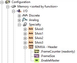
.FrameCounter (read-only) is an Unsigned Byte. If the port is configured to operate as a DMX512 Controller this value shows the total number of DMX512 packets that have been sent. If the port is configured to operate as a DMX512 Slave this value contains the number of DMX512 packets that have been received. Since this value is only a Byte containing a value between 0 and 255, the value will roll over quite often.
.FrameSize (read / write) is an Unsigned Word . If the port is configured to operate as a DMX512 Controller this value sets how many of the 512 bytes to send in the out-gong packet. If the port is configured to operate as a DMX512 Slave this value contains the number of bytes that were received in the last packet.
.EnableMaster (read / write; only applicable if the port is a DMX512 Controller) is a Bit that, when ON, will cause the DMX512 Controller to begin sending packets containing the number of bytes defined in .FrameSize, if OFF, no packets will be sent.
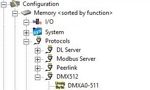
DMX512 Memory Block
For each port that is configured as either DMX512 option, a memory block of 512 Unsigned Bytes is automatically created, default name is DMXA / DMXB / DMXC / DMXD, the size is fixed at 512 Bytes. These default names can be changed if needed.
Using SERIO as a DMX512 Controller
Assuming the serial port on the BX-SERIO has been configured as a DMX512 Controller and the cabling between that port and all of the DMX512 slaves is correct and operational, the network is ready to begin processing DMX512 data. Remember that each BYTE in the DMX512 Controller's associated memory block represents a channel; for example, DMXA0 = channel 1, DMXA1 = channel 2, DMXA511 = channel 512. Each channel is an Unsigned Byte, which means it can have a value between 0 and 255.
Begin by putting the BRX CPU into RUN mode, then set the .FrameSize member of the Controller's associated structure to the total number of bytes to send. This can be any number between 0 (no data bytes will be sent) and 512 (all of the data bytes in the memory block are being sent). This value can be changed at any time. The number of bytes of data being sent directly impacts the update rate. A maximum-sized packet - with 512 bytes of data - takes approximately 23 ms to send, this equates to a maximum refresh rate of about 44 Hz. Higher refresh rates can be achieved by sending packets with fewer than 512 bytes of data.
Next, turn ON the Controller's associated structure member .EnableMaster. As soon as this happens the BRX CPU will begin sending the .FrameSizenumber of bytes of data from the Controller's associated memory block. It will continually send the data as long as .EnableMaster remains ON.
Note: each time the BRX CPU transitions from RUN mode to STOP mode, .EnableMaster will be set OFF and .FrameSize will be reset to 512. These values need to be set back ON each time the PLC transitions from STOP to RUN mode to resume sending packets.
The .FrameCounter field in the Controller's associated structure will increment by one each time a packet is successfully sent.
Using SERIO as a DMX512 Slave
Any time the BRX CPU is in RUN mode, each DMX512 Slave port will be enabled and will be capable of receiving data packets from a DMX512 Controller. Each BYTE in the DMX512 Slave's associated memory block represents a channel; for example, DMXA0 = channel 1, DMXA1 = channel 2, DMXA511 = channel 512. Each channel is an Unsigned Byte, which means it can have a value between 0 and 255.
The Slave's .FrameCounter structure field will increment by one each time a packet is received
The Slave's .FrameSize structure field will contain the number of bytes in the last received packet.
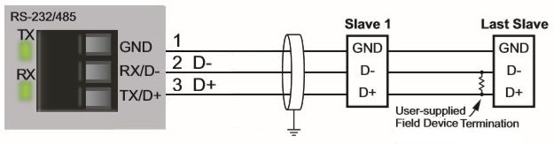
Connections
The serial ports of the BX-SERIO use a 3-pin terminal strip connectors. When the port is configured for either DMX512 option the Port Type is fixed at RS-485, which has the following port pin out:
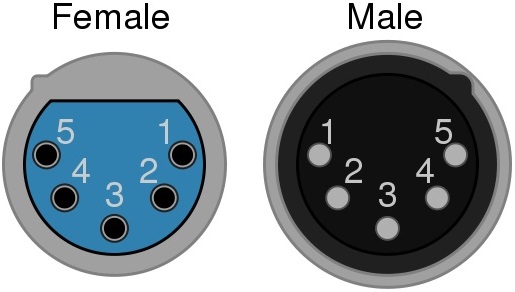
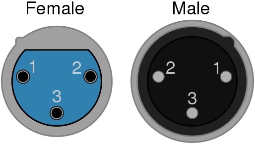
Many of the DMX512 devices that use DMX512 protocol will have XLR connectors. The pin outs for two of the most popular connectors are shown below:
See Also:
BX-SERIO 4 Port Serial Communication Module