Topic: DMD0141

PID - Closed Loop Controller
The Closed Loop Controller (PID) instruction implements a Proportional, Integral, and optionally Derivative control algorithm in the Do-more CPU. The PID instruction calculates an "error" value as the difference between a measured process variable (PV) and the desired setpoint (SP). The PID controller attempts to minimize the error by adjusting the PID Output, which then affects the process control inputs.
The general function of the PID instruction is to use a continuous feedback loop to keep the process flowing normally by taking corrective action whenever there is a deviation from the desired value (SP) of the process variable (PV) such as, rate of flow, temperature, voltage, etc. The resulting .Output value is calculated as a percentage value in the range of 0.0 to 100.0.
Instruction Inputs:
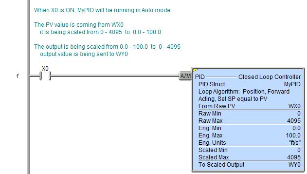
The PID Loop's mode (Auto or Manual) is controlled by the power-flow of the PID instruction's single ladder logic input labeled (A/M) (Auto mode / Manual mode).
If the input logic is ON, the PID instruction is enabled and the loop's Mode is set to Auto. In Auto mode the loop runs the PID calculation to generate new .Output value every Sample Time interval.
If the input is OFF, the loop's Mode is set to Manual. In Manual mode the loop IS NOT running the PID calculation, meaning the .Output value remains unchanged by the loop. While the PID loop is in Manual mode it is expected that an operator or other intelligent source is manually controlling the output by observing the PV and writing data to .Output as necessary to keep the process under control.
Parameters:
Note: Use the F9 key or click the 'three dot box' at the right edge of the parameter field to open the Default Element Selection Tool (the Element Picker or the Element Browser) or use the Down-Arrow key (Auto-Complete) on any parameter field to see a complete list of the memory locations that are valid for that parameter of the instruction.
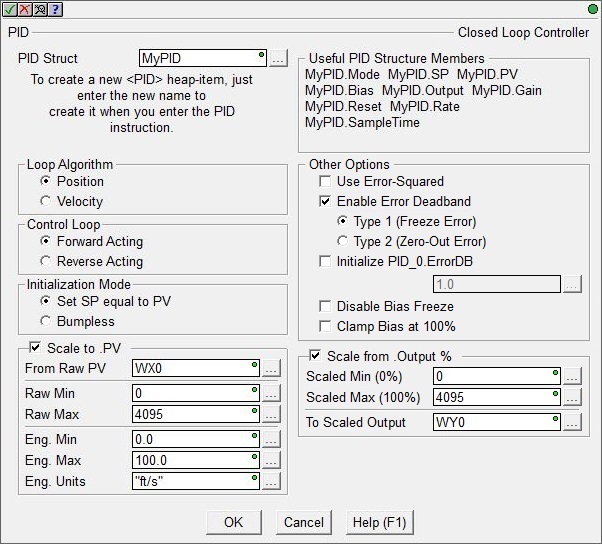
PID Struct is a user-assigned name
to uniquely identify the PID Loop. This can be a either a new Heap Item![]() A Heap item and it's associated memory are not preallocated in a default Memory configuration. They are single items as opposed to one entry of a memory block. A Heap Item can be created in the Memory Configuration or be created when the instruction using it is added to the ladder diagram.
to create, or the name of a PID Struct that has already been created.
A Heap item and it's associated memory are not preallocated in a default Memory configuration. They are single items as opposed to one entry of a memory block. A Heap Item can be created in the Memory Configuration or be created when the instruction using it is added to the ladder diagram.
to create, or the name of a PID Struct that has already been created.
Note: choosing to create a new heap item will change the System Configuration. Changes to the System Configuration can only be saved to the Do-more controller when it is in PROGRAM mode. Additional Run mode updates can not be performed until these System Configuration changes have been saved to the controller. For more information on heap items and pre-allocating one or more PID loops refer to the Memory Configuration section in the System Configuration utility.
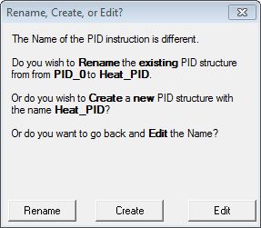
If the PID Struct field is changed, the dialog at the right will be displayed.
Selecting Rename will rename the existing PID Struct, this will not cause a change to the System Configuration. One situation where this would occur is after a copy / paste operation of an existing PID structure and the Struct of the pasted PID loop needs to be changed.
Selecting Create will create a new heap item, and the existing PID Struct will not be affected. This will cause a change to the System Configuration which can only be saved to the Do-more controller when it is in PROGRAM mode.
Selecting Edit will return to the instruction editor.
Loop Algorithm selects the type of calculation to be done:
-
Select Position to compute the actual position. This is the choice for most applications which include heating and cooling loops as well as most position and level control loops.
-
Select Velocity to compute the change in position. A typical velocity control will consist of a process variable such as a flow totalizer in a flow control loop.
Control Loop selects
the relationship between the Output value and the Error value:
-
Select Forward Acting if the output is driven in the same direction as the error. A forward (direct) acting control loop means that whenever the .Output value increases, the process variable will also increase.
-
Select Reverse Acting if the output is driven in the opposite direction from the error. A reverse acting control loop means that whenever the .Output value increases, the process variable will decrease.
Initialization Mode : a bumpless
transfer from manual mode to automatic mode is achieved by preventing
the control output from changing immediately after the mode change.
-
Set SP equal to PV automatically sets the Output equal to the Bias and the Setpoint equal to the Process Variable when control switches from manual to automatic.
-
Bumpless automatically sets the Output equal to the Bias when control switches from manual to automatic.
Enabling the Scale to .PV option will scale the raw input value to engineering units before it's used as the Process Variable (.PV). This calculation is made in both Automatic and Manual modes.
From Raw PV is the location where the raw version of the Process Variable (.PV) is stored. This can be any readable numeric location but is typically a raw analog input location (WX).
Raw Min is the minimum raw data point to use in the scaling algorithm. This can be any constant value or any readable numeric location.
Raw Max is the maximum raw data point to use in the scaling algorithm. This can be any constant value or any readable numeric location.
Eng Min is the engineering data point that equates to the Raw Min parameter value to use in the scaling algorithm. This can be any constant value or any readable numeric location.
Eng Max is the engineering data point that equates to the Raw Max parameter value to use in the scaling algorithm. This can be any constant value or any readable numeric location.
Eng Units is an 8 character string that will be displayed on the PID View. This can be a String Literal
Zero or more characters enclosed in double quotes, as in "hello", and may include both simple escape sequences (such as \t for the tab character) and hexadecimal data (such as 0xAA). any of the system-defined Short Strings, or system-defined Long Strings, or user-defined Strings.
Other Options specify optional
processing of the Error term If both Error Squared and Error Deadband
are enabled, the error will be squared first, then the Error Deadband
calculation will be made.
-
Use Error Squared : a loop with Error Squared enabled is less responsive than a loop using just the error value; however, it will respond faster with a large error. The smaller the error, the less responsive the loop. The sign of the Error term (positive or negative) is maintained in the Error Squared value.
-
Enable Error Deadband : Error Deadband reduces the effect of a noisy Process Variable on the loop output. The Error Deadband value is specified in the .ErrorDB member of the PID's associated structure, for example MyPID.ErrorDB. The ErrorDB value needs to be in the same units as the Setpoint and the Process Variable.
When determining the deadband there are two Error values to keep in mind: Raw Error is the difference between the Setpoint and the Process Variable, and Effective Error which is the error value used in the PID calculation after Error Deadband is applied. When Enable Deadband Error is OFF, the Raw Error is passed directly into the PID calculation. When Enable Deadband Error is ON, a deadband is applied to Raw Error to create the Effective Error, which is then passed to the PID calculation. For example, with an Error Deadband value of 1 and an Effective Error of 5, any Raw Error value between 4 and 6 would produce no change for the Effective Error. If Raw Error were measured at 3, Effective Error would change to 4. The full Error Deadband value is evaluated the same above and below the Error value. See chart below.
-
Type 1 (Freeze Error) means the Error term will not change when the PV gets within the Deadband limits.
-
Type 2 (Zero-Out Error) means the Error term is set to 0.0 when the PV gets within the Deadband limits.
-
-
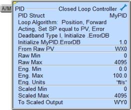
Click Initialize <PID>.ErrorDB to have the PID instruction initialize the .ErrorDB value in the PID loop's associated structure to the specified value each time the PID Mode changes from Manual to Auto. The .ErrorDB value can be any constant or any numeric memory location.
-
If Disable Bias Freeze is enabled the PID algorithm will continue changing the Bias even though the computed normalized output goes outside the range of 0.0 to 100.0.
-
If Clamp Bias at 100% is enabled the PID algorithm will not let the Bias value go above 100.0%.
Scale from .Output % enables optional scaling of the Output value (.Output) before it's stored in the designated analog output location. The raw .Output value has a range of 0.0 to 100.0. This calculation is made in both Automatic and Manual modes.
Scaled Min is the minimum scaled value to use in the scaling algorithm corresponding to when .Output value equals 0.0. This can be any constant value or any readable numeric location.
Scaled Max is the maximum scaled value to use in the scaling algorithm corresponding to when .Output value equals 100.0. This can be any constant value or any readable numeric location.
To Scaled is the output location to store the scaled Output value. This can be any writable numeric location but is typically a raw analog output value (WY). Note: because this scale calculation is made in Manual mode, you cannot write directly to the To Scaled location; you must write to the PID loop's .Output structure member which will then get reflected in the calculated To Scaled value.
Closed Loop Controller (PID) Structure Members:
Each Closed Loop Controller (PID) instruction has an associated PID structure. The structure's fields are updated each time the PID instruction is executed. The Input fields of a PID loop structure are used for writing configuration data to the PID loop, to manage the PID loop's mode, and to manage the Autotune process. The structure's Output fields are calculated by the PID algorithm and can be used to monitor the loop's response to its configuration and the input values.
The following is a list of the fields that are programmatically accessible for each PID Loop instruction:
|
Field |
Field Type |
Data Type |
||
|
.PV |
Input |
Process Variable |
Real |
The Process Variable (PV) is the input value that is being measured, typically from an analog input.
|
|
.SP |
Input |
Setpoint |
Real |
The Set point is the target value that the PID loop wants the Process Variable (PV) to reach.
|
|
Input |
Proportional |
Real |
The Gain (P) value sets the output of the PID loop proportional to the
change in the process variable (PV).
|
|
|
.Reset |
Input |
Integral |
Real |
The Reset (I) value determines how the PID loop output will change based
on the amount of time (in seconds) there is an error between set point
(SP) and the process variable (PV).
Larger values eliminate steady state errors more slowly. The trade-off is larger overshoot: any negative error integrated during transient response must be integrated away by positive error before reaching steady state.
The time base is seconds, so a value of 1.0 = 1 Second, 0.5 = 500ms, etc.
A value of 0 disables the effect of this term in the PID calculation
|
|
.Rate |
Input |
Derivative |
Real |
The Rate (D) value determines how the PID loop will respond based on
the rate of change in the process variable (PV).
The time base is value / second, so a value of 1.5 = 1.5 / second, 0.75 = 0.75 / second, etc.
|
|
.Bias |
Output |
Bias |
Real |
In some modes the Bias is used to provide bumpless transfer from automatic to manual mode, and vice versa. Bias is set equal to the actual output value (with consideration of the Error term) when the loop is switched from manual to automatic mode.
|
|
.Output |
Output |
Real |
The output value from the loop calculation as a percentage in the range 0.0 to 100.0.
|
|
|
.ErrorDB |
Input |
Error Deadband |
Real |
The Error Deadband designates the area around Error value where no action will occur. The error deadband is the same above and below the setpoint and should be in the same units as the Process Variable.
If 'Enable Error Deadband' has been selected in the PID instruction, this is where the deadband value is entered.
If 'Initialize Error Deadband' is enabled in the PID instruction, it will initialize the .ErrorDB value in the PID loop's associated structure to the value specified in the instruction each time the PID Mode changes from Manual to Auto.
|
|
Input |
Real |
If the magnitude of the loop calculation exceeds the derivative gain limit, the derivative component will be clamped at the specified limit.
|
||
|
.SampleTime |
Input |
The SampleTime value designates how often the loop calculation is performed. The value is specified in milliseconds.
|
||
|
.Mode |
Output |
Loop More |
Bit |
0 = Loop is in Manual Mode
|
|
Output |
|
Bit |
0 = No Autotune in progress
.AutoTuning gets set ON at the rising edge of .Tune
.AutoTuning gets cleared upon completion of a tuning operation, and will be reset when .Tune is dropped
|
|
|
Output |
Autotune Complete |
Bit |
0 = Autotune in progress 1 = the last auto-tune cycle completed successfully
|
|
|
Output |
Bit |
0 = Autotune attempt completed successfully
The following conditions will cause the .AutoTuningErr bit to be ON at the completion of an Autotune attempt:
Closed Loop Method
|
||
|
Output |
Loop calculation ran this scan |
|
0 = Loop Calculation was not performed on the current PLC scan
|
|
|
.Tune |
Input |
Autotune |
Bit |
Initiates an Autotune: 0 = Stop Autotune
This Request Bit is typically controlled by the Autotune process in the PID View, but it can be manually set by any of the normal Bit set / reset methods.
A rising edge of this Bit will initiate an auto-tune cycle. Turning this Bit OFF before the completion of the Autotune cycle will abort the current Autotune attempt, and .AutoTuning, .AutoTuneComp, and .AutoTuneErr will be OFF.
.AutoTuning gets set of the rising edge of .Tune, and both .AutoTuneComp and .AutoTuneErr will be OFF.
.AutoTuning gets cleared and .AutoTuneComp and .AutoTuneErr get set upon completion of the tune operation.
When Autotune process finishes .AutoTuning will be OFF; .AutoTuneComp will be ON; .AutoTuneErr will be OFF if the Autotune worked, or ON if it failed.
These three status Bits get reset when .Tune is set OFF.
|
|
Input |
Bit |
Designates whether the Autotune should use an Open Loop or Closed loop
algorithm:
|
||
|
Input |
Tuning Parameters |
Bit |
Designates whether the Autotune should use a PI or PID calculation:
|
|
|
.LastError |
Output |
Error value |
Real |
The computed Error (or error squared if specified) value. This value is the difference between a measured process variable (PV) and a desired setpoint (SP).
|
Status Display:
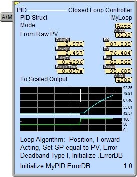
The yellow triangle in the upper left corner indicates this is a Multi-Scan instruction.
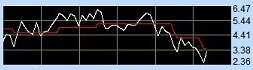
When the ladder status is ON (Debug -> All Status On), in addition to the key PID numeric status values being displayed, the Closed Loop Controller instruction also displays two small trends that show the PID structure's values graphically. The first graph shows the Set Point and Process Variable input values. The second graph shows the Control Output value.
To turn off the trend display, go to the View -> Options menu, select the Ladder tab, then uncheck the Show Trend Status selection.
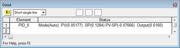
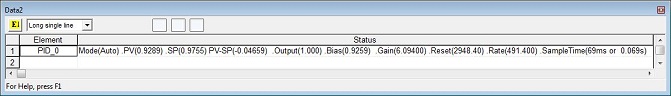
Data View Display Formats:
The Data View dialog in Do-more Designer has four display formats for a Closed Loop Controller (PID) structure, two that offer different orientations (single line and multi-line) and two that offer different numbers of data points (short and long). These formats are for display purposes only, the PID Loop variables cannot be edited when displayed using any of the formats. Use the individual structure members individually to change any writable member.
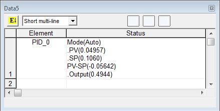
Short Multi-Line (the default):
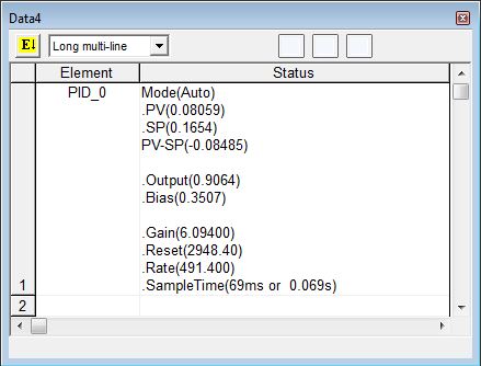
Long Multi-Line:
Related Instructions:
DEADBAND - Set Outside Deadband
INTEGRAT - Integrate Over Time
PID - Closed Loop Controller
PIDINIT - Set PID Tuning Constants
TIMEPROP - Time Proportional Control
See Also:
Related Topics:
Getting Started with PID Loops
Using the Do-more PID Process Simulator
Rung Example: