Topic: DMD0243

Using the PID Process Simulator
The Do-more Designer Simulator (DmSim) includes a PID Process simulator that can be used to demonstrate the process control abilities of the controller, or for testing potential changes to existing control solutions by working with the process control instructions in a simulation environment before deploying the control solution to a Do-more controller. The PID process simulator uses a first order filter and a dead time calculation to provide the simulated PID loop response.
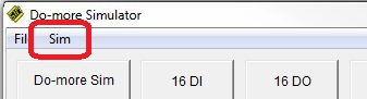
The PID Process Simulator is opened by clicking 'Sim' on the toolbar of the Simulator and selecting Setup PID Process Simulator.
The PID Process Simulator requires two ladder logic instructions in the Simulator before it can operate properly. These two instructions ( a PID and a SCALE ) will use the I/O in the simulator to provide space for the PID calculation and user input.
Click the What else do I need to do? button to display a dialog that details the instructions that must be added to the ladder program to make the PID process simulator work.

Note: an example project named PID1.Dmd is shipped with Do-more Designer that contains the required ladder logic components that are described below.
A Closed Loop Controller (PID) instruction configured as shown below:
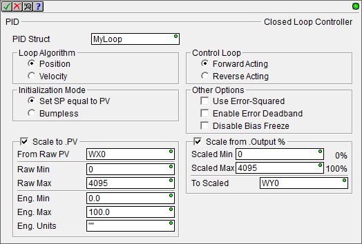
give it the name MyLoop
set Position, Forward Acting, Set SP equal to PV, and do NOT select any other options
check the 'Scale to .PV' box to use WX0 as the Process Variable
make sure it's raw scaled range is 0 to 4095, and it's Eng scaled range is 0.0 to 100.0
check the 'Scale from .Output %' box to use WY0 as .Output
make sure it's scaled range is 0 to 4095 and To Scaled is set to WY0
Note: Make sure to use floating point representations of the 0.0 and 100.0 numbers (not 0 and 100) in the SCALE portions of the instruction.
A Scale Value (SCALE) instruction to use WX1 as a user-controllable Set Point (SP).
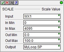
set the Input to WX1
make sure the In range is 0 to 4095
make sure the Out range is 0.0 to 100.0
make sure the output is set to MyLoop.SP
Note: Make sure to use floating point representations of the 0.0 and 100.0 numbers (not 0 and 100) in the SCALE instruction.
The PID Process Simulator will use:
-
the Simulator's analog input WX0 to make the loop calculations for the Process Variable (PV)
-
the Simulator's analog output WY0 to make the value available to the rest of the program (Output)
-
the Simulator's analog input WX1 to provide a manually adjustable Set Point (SP) value.
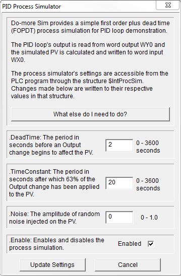
There is a built-in structure for the PID Process Simulator (called $IntProcSim) that contains the following fields used to perform the simulation. This dialog will write values for these fields or they can be set by the ladder logic in the controller.
.DeadTime - The period (in seconds) before an output change begins to affect the PV. This is the dead time portion of the process simulation calculation. The range of values is 0 to 3600 seconds.
.TimeConstant - The period (in seconds) after which 63% of the Output change has been applied to the PV. The range of values is 0 to 3600 seconds.
.Noise - the PID process simulator can inject some random noise into the system. Change the value from 0 to a number between 0.0 and 1.0 to specify the amplitude of the random noise to be injected on the PV (0.0 is less noise than 1.0).
.Enable - starts and stops the process simulation. If Enabled is checked the process simulation is running.
Update Settings - click this button to write the above three values to the Simulator.
Cancel - click this button to close the PID Process Simulator.
See Also:
Process Control Instruction Set
Using the PID Process Simulator
Related Topics:
PID Calculation and Tuning Constants
PIDINIT - Set PID Tuning Constants
Alarm Handlers
Input and Output Value Limiters
DEADBAND - Set Outside Deadband
Noise Suppression
INTEGRAT - Integrate Over Time
Ramp/Soak Profiles - up to 250 steps per Profile
Input and Output Scaling
Analog Control using a Discrete Output
TIMEPROP - Time Proportional Control