Topic: DMD0144

TIMEPROP - Time Proportional Control
The Time Proportional Control (TIMEPROP) instruction is used to convert the continuous control output variable (interpreted as a percentage) to a time proportioning control value that suitable for a discrete output.
Time-proportional control is a form of pulse-width modulation, which is a mathematical technique that allows a controller to use an on / off or discrete actuator as if it were a continuous actuator capable of generating control outputs anywhere between 0% and 100%. This control method is used to turn the actuator on and off for periods of time that are proportional to the desired control output. A good example of time proportional control is a hot-air balloon following a path (the Set Point) across some mountains. The balloon pilot turns the burner on and off alternately, which is his control output. The large mass of air in the balloon effectively averages the effect of the burner, converting the bursts of heat into a continuous effect: slowly changing balloon temperature and ultimately the altitude, which is the process variable.
The Closed Loop Controller (PID) instruction generates a smooth control output signal across a numerical range, typically 0% to 100%. This is called continuous control because the output is continuously driven at some level. PID control is applied in an ON / OFF control system by adding a time base within the controller. For each preset time interval, the Cycle Time, the controller will proportion the ON and OFF time depending on the magnitude of the output and the PID tuning values selected.
ON Time = Cycle Time * ((Continuous
Input - 0% Min. Range) / (100%
Max. Range - 0% Min. Range))
OFF Time = Cycle Time - ON Time
Parameters:
Note: Use the F9 key or click the 'three dot box' at the right edge of the parameter field to open the Default Element Selection Tool (the Element Picker or the Element Browser) or use the Down-Arrow key (Auto-Complete) on any parameter field to see a complete list of the memory locations that are valid for that parameter of the instruction.
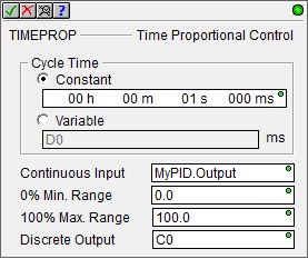
Cycle Time - specifies the
amount of time that will be divided into the ON and an OFF portions. This values should never exceed the Sample Time of the PID Loop that is generating the continuous input value. When determining this value, a value that is 1/10 of the Sample Time of the
PID Loop is a good starting point. The closer this value is to the PID Loop Sample Time the longer it takes for changes the Loop's output to show up in the TIMEPROP's output.
Constant - specified using the Time format (HH : MM : SS : mmm). The maximum Cycle Time value in this form is 569 hours, 31 minutes, 23 seconds, and 647 milliseconds. If needed, the value entered for the Cycle Time will be normalized to its standard value. For example, if you entered a value of 97 Seconds, that value will be converted and displayed as 1 Minute and 37 Seconds. When editing the Constant Preset value, the following keystrokes are available to make entering the value easier and faster:
h takes you to the Hours field, m takes you to the Minutes field, s takes you to the Seconds field, mm takes you to the Milliseconds field.
Variable - selects a location that contains the total number of milliseconds desired for the Cycle Time. This can be any readable numeric location.
Continuous Input - selects the location that contains the Input value. This can be any readable numeric location, but is typically the output of a Closed Loop Controller (PID) instruction ( <PID Reference>.Output ).
The time proportioning control must match the resolution of the Continuous Input (typically 0% to 100%). For example, when using PID .Output values the range would be 0.0 to 100.0, and for 12-bit analog inputs the range would be 0 to 4095. The following two fields allow for adjusting the scale factor:
0% Min Range - specifies the minimum value of the Continuous Input Range. This can be any constant value or any readable numeric location.
100% Max Range - specifies the maximum value of the Continuous Input Range. This can be any constant value or any readable numeric location.
Discrete Output - specifies the BIT location in the PLC that will be turned ON and OFF. This can be any writable Bit location.
Termination Scan Behavior:
Termination behavior describes the actions that the TIMEPROP instruction perform when they stop executing. If the TIMEPROP instruction is contained within a Program, a Task, or a Stage the specified Discrete Output will be turned OFF during the termination scan of the containing element. Refer to the Help topic on Termination Behavior for detailed information on the programming elements that have termination logic.
Status Display:
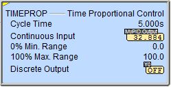
The yellow triangle in the upper left corner indicates this is a Multi-Scan instruction.
See Also:
DEADBAND
- Set Outside Deadband
INTEGRAT
- Integrate Over Time
PIDINIT
- Set PID Tuning Constants
TIMEPROP - Time Proportional Control
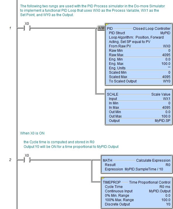
Rung Example: