Topic: DMD0245

Help File Version: 2.9.4.37

Process Control Instruction Set


Process Control Instruction Set

The Do-more environment utilizes what we refer to as the Tinker-Toy™ approach to providing options that can handle various Process Control requirements. Rather than embedding the alarm handlers and Ramp / Soak tables within the PID instruction itself, these are all handled by separate instructions, allowing the proper level of customization for whatever control algorithms are used. The Do-more controller provides a full complement of Process Control related instructions that includes:

PID Calculation and Tuning Constants

PID - Closed Loop Controller


PIDINIT - Set PID Tuning Constants

Alarm Handlers

ALDEV - Deviation Alarm

ALHILO - High / Low Alarm

ALRATE - Rate of Change Alarm

Input and Output Value Limiters

CLAMP - Limit Range

DEADBAND - Set Outside Deadband

Noise Suppression

FILTER - First Order Filter

INTEGRAT - Integrate Over Time

Ramp / Soak Profiles - up to 250 steps per Profile

RAMPSOAK - Ramp-Soak Profile

Input and Output Scaling

SCALE - Scale Value

LERP - Linear Interpolation

SLOPE- Calculate Slope

Emulate Analog Level Control with a Discrete Output Device

TIMEPROP - Time Proportional Control


Process Control Utilities

The Do-more Designer programming environment has several utility programs to assist in the configuration, tuning and monitoring of PID loops:


The PID View - is where the majority of the work related to configuring, tuning, and monitoring PID loops will be done. The PID View is opened by selecting Debug-> PID View from the Online Toolbar, or right-clicking on any PID instruction in a ladder diagram and select Trend Instruction from the pop-up menu, or double-clicking on the PID Overview graphic for that PID loop.

The PID View is broken into three sections: the PID Data form which displays the current configuration of the underlying PID Loop, and two trend graphs (one with the .PV and .SP fields, and one with the .Output and .Bias fields) to see the results of the configuration and tuning efforts.
 

Using Auto-tune - the Do-more controller provides an automatic tuning function to help in achieving optimal P, I, and D values. Any of the terms set incorrectly can cause the process to be unstable, or very slow to control.
 

The PID Overview - is a container that will display a boilerplate for each Closed Loop Controller (PID) instruction used in a Do-more Designer project. The boilerplate for each PID Loop displays the most commonly needed runtime values and alarming information (if available).
 

Using the PID Process Simulator - the Do-more Simulator includes a PID Process simulator that can be used to demonstrate the process control abilities of the controller, or for testing potential changes to existing control solutions by working with the process control instructions in a simulation environment before deploying the control solution to a Do-more controller. The PID Process simulator uses a first order filter and a dead time calculation to provide the simulated PID loop response.


PID Structure Fields

Each Closed Loop Controller (PID) in a project has an associated data structure that is used to store its data.
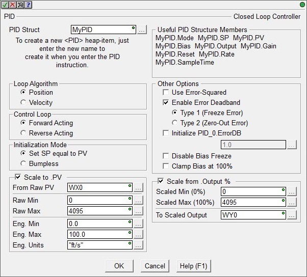


Each of these structures contains members ("dot" fields) that can be used elsewhere in your ladder program. These structure members are updated each time the PID instruction is executed. The syntax for using them in other places in the project is <PID structure>.< member field>.


The Input fields of a PID loop are used for writing configuration data to the PID loop, to manage the PID loop's mode, and to manage the Autotune process. The Output fields of a PID loop are used to monitor the loop's response to its configuration and the input values. These fields are updated each time the PID instruction is executed as part of the ladder logic scan. Refer to the following chart for complete lists of the input and output fields, their data types, and acceptable ranges:


The Input fields of a PID loop are used for writing configuration data to the PID loop, to manage the PID loop's mode, and to manage the Autotune process. The Output fields are calculated by the PID algorithm and can be used to monitor the loop's response to its configuration and the input values. These fields are updated each time the PID instruction is executed as part of the ladder logic scan.


The following is a list of the"dot" fields that are programmatically accessible for each Closed Loop Controller instruction:


Field

Field Type

Field Name

Data Type

Description

.PV

Input

Process Variable

Real

The Process Variable (PV) is the input value that is being measured, typically from an analog input.


.SP

Input

Setpoint

Real

The Set point is the target value that the PID loop wants the Process Variable (PV) to reach.


.Gain

Input

Proportional

Real

The Gain (P) value sets the output of the PID loop proportional to the change in the process variable (PV).

Larger values mean a faster output response since the larger the error, the larger the proportional term compensation. But, an excessively large proportional gain can lead to process instability and oscillation.


.Reset

Input

Integral

Real

The Reset (I) value determines how the PID loop output will change based on the amount of time (in seconds) there is an error between set point (SP) and the process variable (PV).


Larger values eliminate steady state errors more slowly. The trade-off is larger overshoot: any negative error integrated during transient response must be integrated away by positive error before reaching steady state.


The time base is seconds, so a value of 1.0 = 1 Second, 0.5 = 500ms, etc.


A value of 0 disables the effect of this term in the PID calculation.


.Rate

Input

Derivative

Real

The Rate (D) value determines how the PID loop will respond based on the rate of change in the process variable (PV).

Larger values decrease overshoot, but slow down transient response and may lead to instability due to signal noise amplification in the differentiation of the error.


The time base is value / second, so a value of 1.5 = 1.5 / second, 0.75 = 0.75 / second, etc.


.Bias

Output

Bias

Real

In some modes the Bias is used to provide bumpless transfer from automatic to manual mode, and vice versa. Bias is set equal to the actual output value (with consideration of the Error term) when the loop is switched from manual to automatic mode.


.Output

Output

Control Output

Real

The output value from the loop calculation.


.ErrorDB

Input

Error Deadband

Real

The Error Deadband designates the area around Error value where no action will occur. The error deadband is the same above and below the setpoint. If 'Enable Error Deadband' has been selected in the PID instruction, this is where the deadband value is entered.


.DGainLmt

Input

Derivative Gain Limit

Real

If the magnitude of the loop calculation exceeds the derivative gain limit, the derivative component will be clamped at the specified limit.


.SampleTime

Input

Loop Sample Time

Integer

The SampleTime value designates how often the loop calculation is performed. The value is specified in milliseconds.


.Mode

Output
(read-only)

Loop More

Bit

0 = Manual Mode
1 = Automatic Mode


.AutoTuning

Output
(read-only)

Autotune Mode


Bit

0 = No Autotune in progress
1 = Autotune in progress


.AutoTuneComp

Output
(read-only)

Autotune Complete

Bit

0 = Autotune complete

1 = Autotune is running


.AutoTuningErr

Output
(read-only)

Autotune Error

Bit

0 = Autotune completed successfully
1 = Autotune did not complete successfully, loop is not tuned.


.RanThisScan

Output

Loop calculation ran this scan


0 = Loop Calculation was not performed on the current PLC scan
1 = Loop Calculation was performed on the current PLC scan


.Tune

Input

Autotune

Bit

Initiates an Autotune:

0 = Stop Autotune
1 = Start Autotune


.TuningAlg

Input

Tuning Algorithm

Bit

Designates whether the Autotune should use an Open Loop or Closed loop algorithm:
0 = Closed Loop
1 = Open Loop


.TunedParms

Input

Tuning Parameters

Bit

Designates whether the Autotune should use a PI or PID calculation:
0 = PI
1 = PID


.LastError

Output
(read-only)

Error value

Real

The Computed Error value, that is, the difference between a measured process variable (PV) and a desired setpoint (SP).


See Also:

Process Control Basics


PID Control in Do-more


Process Control Instruction Set


The PID View


Using Autotune


The PID Overview


Using the PID Process Simulator