Topic: DMD0142

RAMPSOAK - Ramp / Soak Profile
The Ramp / Soak Profile (RAMPSOAK) instruction contains a table of sequential operations that will move the user-specified setpoint value through a predefined set of values at prescribed time intervals. A Ramp / Soak Profile can contain from 1 to 50 individual steps. Each of the individual steps is executed sequentially to modify the value of the Set Point variable.
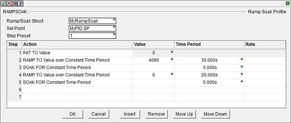
Row Editor Keys:
The following functions are used to manage the rows in the instruction: Ok - closes the editor, saving any changes, and Cancel - closes the editor, discarding any changes. Insert adds a new row in the instruction before the currently selected row, and Remove - removes the currently selected row. Move Up / Move Down moves the currently selected row up one row or down one row respectively.
Shortcuts & Hot Keys:
When editing the Time Period value, the following keystrokes are available to make entering the value easier and faster: h takes you to the Hours field, m takes you to the Minutes field, s takes you to the Seconds field, and mm takes you to the Milliseconds field.
Instruction Inputs:
The Ramp / Soak Profile (RAMPSOAK) instruction has the following three ladder logic input legs:
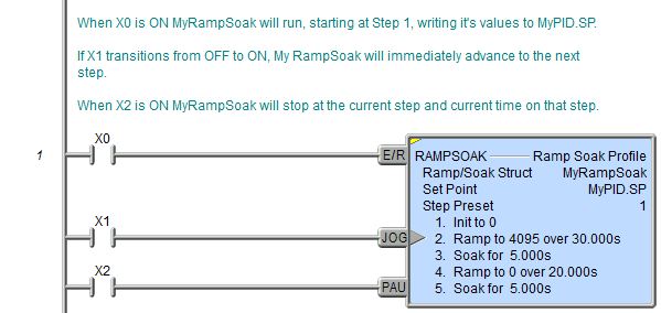
The first input leg (E/R) is the ENABLE / RESET input. If the input logic is ON, the Ramp / Soak will start sequencing through the steps, beginning with step 1. When this input logic is OFF, the Ramp / Soak will reset the instruction by resetting the current step to the Step Preset value (usually 1).
The second input leg (JOG)
is the JOG input. This is edge
triggered![]() Each time the input logic transitions from OFF to ON this instruction will execute. With each execution, this instruction will run to completion even if the input logic transitions to OFF before the instruction completes. meaning that each time this input logic transitions from
OFF to ON execution will manually move to the next step in the Ramp / Soak
Profile, regardless of whether the current step has completed or not.
Each time the input logic transitions from OFF to ON this instruction will execute. With each execution, this instruction will run to completion even if the input logic transitions to OFF before the instruction completes. meaning that each time this input logic transitions from
OFF to ON execution will manually move to the next step in the Ramp / Soak
Profile, regardless of whether the current step has completed or not.
The third input leg (PAU) is the PAUSE input. When the input logic is ON, this input will freeze the execution of the RAMPSOAK Profile in the current step. Execution will continue from the point it was paused when the input logic is OFF.
Parameters:
Note: Use the F9 key or click the 'three dot box' at the right edge of the parameter field to open the Default Element Selection Tool (the Element Picker or the Element Browser) or use the Down-Arrow key (Auto-Complete) on any parameter field to see a complete list of the memory locations that are valid for that parameter of the instruction.
Ramp / Soak Struct specifies the Rampsoak structure that will be used by this Ramp / Soak Profile instruction. This can be a either a new Heap Item to create, or the name of Ramp / Soak Profile Structure that has already been allocated.
If the Ramp / Soak Structure field is changed for any reason, this dialog will be displayed:
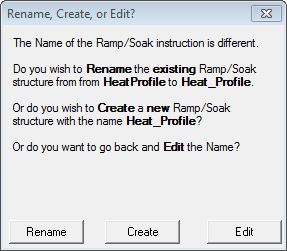
Rename will simply rename the existing Ramp / Soak Struct, this will not cause a change to the System Configuration. This will cause a change to the System Configuration which can only be saved to the Do-more CPU while it is in PROGRAM mode.
Create will create a new heap item, and the existing Ramp / Soak Struct will not be affected. This will cause a change to the System Configuration which can only be saved to the Do-more CPU while it is in PROGRAM mode. One situation where this would occur is after a copy / paste operation of an existing Ramp / Soak Profile and the Struct of the pasted Ramp / Soak Profile needs to be changed.
Edit will return to the instruction editor.
Set Point is the location that will be modified by the Ramp / Soak Profile. This can be any writable numeric location. Since Ramp / Soak instructions are often used to manage the Setpoint of PID loops, a typical value specified here is the <PID Struct>.SP.
Step Preset is the step number where execution begins when the Ramp / Soak Profile is first enabled or when it is reset. This can be any constant (fixed) value from 1 to 50, or any readable numeric location. One situation where using a variable location is quite useful is with a cyclic profile where one or ore of the first step are initialization steps. Initially setting the Step Preset to 1 will run all of the steps, then changing the Step Preset to the first step of the cyclic portion of the profile will skip the initialization steps on subsequent passes through the profile.
Step / Action Table:
The Step / Action table contains up to 50 individual functions the Ramp / Soak instruction can perform and the values required by those functions. There are three classes of functions to choose from: one that sets the Set Point to a fixed value (INIT), one that leaves the Set Point value unchanged for a period of time (SOAK), and one that linearly changes the Set Point value over a period of time (RAMP). The details of each of these types is discussed below:
If you need to initialize the Set Point to a fixed value then use the following step type:
INIT To Value
This step will make the Set Point equal to the specified Value. Value can be any constant (fixed) value or any readable numeric location, for example, the current Process Variable value.
If you need to leave the Set Point value unchanged for a period of time then use one of the following step types:
These steps will not modify the Set Point for the Time Period (in milliseconds) which is specified by either a constant (fixed) value or a value in a readable numeric location.
If your main concern in moving from one Set Point value to the next is making sure the target value is reached within a certain amount of time (implying the rate of change is not the primary issue), then you should use one of the following 'RAMP to Value over Time' or 'ADJUST by Value over Time' step types. These step types will increase or decrease the Set Point linearly across the specified Time Period to the Target Value.
RAMP to Value over Constant Time Period
RAMP to Value over Variable Time Period
The 'RAMP to' steps move the Set Point from its current ABSOLUTE value to the ABSOLUTE target Value. The target value can be any constant value or any readable numeric location.
ADJUST BY Value over Constant Time Period
ADJUST BY Value over Variable Time Period
The 'ADJUST by' steps change the Set Point by an amount RELATIVE to the current Set Point. The target value can be any constant value or any readable numeric location.
The Time Period for either type can be specified as either a Constant (fixed) value specified in the form of HH:MM:SS:mmm, or the value (in milliseconds) can be retrieved from a variable location in the PLC. If the value does come from a variable Value location, the contents of that location are only read when the step is enabled, which means that after that step has started running, you cannot change the Time Period of that step by changing the contents of the variable Value location. The Value location can be any readable numeric location
If your main concern in moving from one Set Point value to the next is controlling the rate at which the changes are applied (implying the time it takes to reach the target Value is not the primary issue), then you should use one of the following 'RAMP to Value at Rate' or 'ADJUST by Value at Rate' step types. These step types will linearly increase or decrease the Set Point at the specified rate until the Set Point reaches the Target Value.
RAMP to Value at Rate / Second
RAMP to Value at Rate / Minute
RAMP to Value at Rate / Hour
The 'RAMP to' steps move the Set Point from its current ABSOLUTE value to the ABSOLUTE target Value.
ADJUST BY Value at Rate / Second
ADJUST BY Value at Rate / Minute
ADJUST BY Value at Rate / Hour
The 'ADJUST by' steps change the Set Point by an amount RELATIVE to the current Set Point. The target value can be any constant (fixed) value or any readable numeric location.
Ramp / Soak Structure Fields:
The structures used by Ramp / Soak Profile instructions provides several status values ("dot" fields) that can be used elsewhere in your ladder program. Their values are updated each time the instruction is processed. The syntax for using them is <Ramp / Soak Structure>.<field name>.
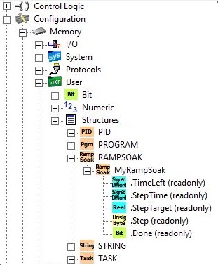
.Step (Read-only) is a signed 32-bit location that contains the currently executing step number in the Profile.
.TimeLeft (Read-only) is a signed 32-bit location that contains the amount of execution time (in milliseconds)
remaining for the currently executing step in the Profile
.StepTarget (Read-only) is a floating point 32-bit location that contains the target value for
the currently executing Ramp step in the Profile
.StepTime (Read-only)
is an unsigned 8-bit location that contains the execution time for the
currently executing step in the Profile
.Done (Read-only) is a Bit location that will be ON when the last step of the Ramp / Soak Profile completes
Status Display:
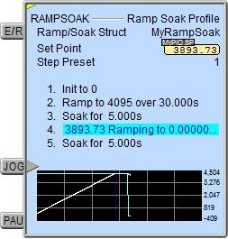
The yellow triangle in the upper left corner indicates this is a Multi-Scan instruction.
The gray triangle at the right end of the input leg indicates the input is edge-triggered, meaning the JOG operation will execute each time the input logic transitions from OFF to ON.
The trend graph that displays the Target Value and the Set Point.
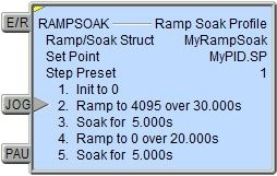
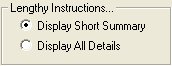
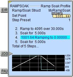
The default setting for Ramp / Soak Profile instructions will have them expand vertically to display all of the steps in the instruction. You can limit the display size of the instruction so that it displays only 4 steps (the current step and the three previous steps) by setting the View -> Options -> Ladder Tab -> Lengthy Instructions... option to 'Display Short Summary'.
The short summary will display 5 lines of the Rampsoak steps and a line that shows the total number of steps.
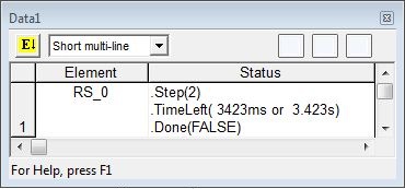
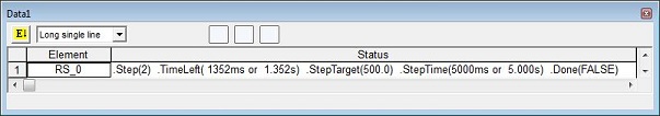
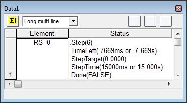
Data View Display Formats:
There are 4 variations of the Data View display of a Ramp / Soak Profile (RAMPSOAK) instruction, each with different amounts of data or different display orientations. These formats are for display purposes only, the Ramp / Soak variables cannot be edited when displayed using any of the formats.
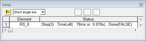
Short Multi-Line (the default):
Long Multi-Line:
See Also:
DEADBAND - Set Outside Deadband
INTEGRAT - Integrate Over Time
PIDINIT - Set PID Tuning Constants
RAMPSOAK - Ramp / Soak Profile
TIMEPROP - Time Proportional Control
Rung Example: