Topic: DMD0371

CALL - Call Subroutine
The Call Subroutine (CALL) instruction is used to execute a user-defined Subroutine code-block. When a Call Subroutine instruction is executed, the ladder logic in the Subroutine runs at the point in the scan where the CALL instruction exists. Once the ladder logic within the Subroutine completes, normal scan execution resumes with the instruction immediately following the CALL instruction.
Subroutines can be called recursively, that is, a Subroutine can execute another instance of itself from within that Subroutine. Subroutines can be nested up to 84 levels deep. Exceeding this limit will generate a runtime error which will cause the CPU to revert to PROGRAM mode.
All Subroutines require a RET - Return Back to Call instruction be the last ladder logic instruction in the code block. One or more RETC - Conditional Return instructions can be used within the body of the Subroutine.

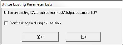
Note: by definition, the ladder logic in a Subroutine is meant to be reused. This is done through multiple CALL instructions, each with different input and output variables. To speed up the editing process, if one or more Subroutines already exist in the project the following message box will ask if you want to Utilize an existing CALL subroutine Input / Output parameter list ? as a starting point for this new CALL instruction.
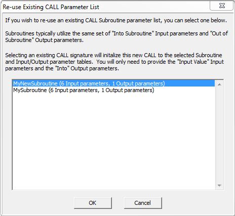
Selecting Yes will open a dialog similar to the following which will list all of the existing Subroutines. Selecting a Subroutine from the list will cause the Into Subroutine parameters and the Out of Subroutine parameter from the selected Subroutine to be copied into the new CALL instruction. You then have to enter only the Input Value parameters and the Into parameter.
Selecting No will immediately bring up an empty CALL instruction where you can begin entering the required parameters.
Don't ask again during this session will prevent this dialog from appearing when subsequent CALL instructions are added to the project during the current editing session.
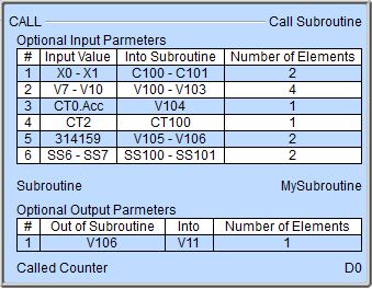
Subroutine is the name of the Subroutine to execute. This can be an existing Subroutine, or you can enter the name of a new Subroutine and it will be created at this time. The Subroutine name can be 1 to 16 characters in length and consist of any combination of alphanumeric characters and underscores ('_', 'a-z', 'A-Z', 0-9), no spaces or punctuation marks are allowed, and must begin with a letter or an underscore.
Optional Input Parameters : it is usually preferred that you use unique memory locations inside the Subroutine. This is done by having the Call Subroutine instruction copy "external" input values to the locations that will be used in the ladder logic in the Subroutine. The Input Value locations are copied to the Into Subroutine locations each time the Call Subroutine instruction is executed. There can be up to 50 Input Parameters.
Note: Use the F9 key or click the 'three dot box' at the right edge of the parameter field to open the Default Element Selection Tool (the Element Picker or the Element Browser) or use the Down-Arrow key (Auto-Complete) on any parameter field to see a complete list of the memory locations that are valid for that parameter of the instruction.
Input Value specifies source memory locations or values that are external to the Subroutine that will be copied to the Into Subroutine locations before the ladder logic in the Subroutine begins to execute. This can be any numeric location, any bit location, any structure, any structure field, or any constant value.
Into Subroutine specifies destination memory locations that are used in the ladder logic in the Subroutine which will receive values from the Input Value locations. The memory type and number should match the memory type and number specified in the Into Value field. This can be any numeric location, any bit location, any structure, or any structure field.
Number of Elements is the number of successive Input Value locations to copy to the Into Subroutine locations. This can be any numeric location or any constant value from 1 to 65535.
If the Input Value is a structure field the Number of Elements is limited to 1.
If the Input Value is a String and the Into Subroutine is a String of a different length the Number of Elements is limited to 1.
If the Input Value is a structure the Into Subroutine type must be a structure of the same type.
If the Input Value type and size do not match the Into Subroutine type and size, the Input Value will be promoted or demoted as necessary to fit the type and size of the Into Subroutine location.
Optional Output Parameters : it is usually preferred that you use unique memory locations inside the Subroutine. This is done by having the Call Subroutine instruction copy "internal" values to external locations that will be used in the rest of the project. The Out of Subroutine locations are copied to the Into locations each time the Call Subroutine execution is complete. There can be up to 50 Output Parameters.
Out of Subroutine specifies source memory locations or values that are generated by the ladder logic in the Subroutine that will be copied to the Into locations after the execution of the ladder logic in the Subroutine is complete. This can be any writable numeric location, any writable bit location, any writable structure, or any writable structure field
Into specifies destination memory locations that are external to the Subroutine which will receive the values generated internal to the Subroutine. The memory type and number should match the memory type and number specified in the Out of Subroutine field. This can be any writable numeric location, any writable bit location, any writable structure, or any writable structure field
Number of Elements is the number of successive Out of Subroutine locations to copy to the Into locations. The same restrictions on the number of elements in the Input Parameter section are also applicable here.
Input Leg selects which of the following power-flow conditions will cause this instruction to run:
- Edge Triggered
means the instruction will run to completion each time the input ladder logic
transitions from OFF to ON.
- Power flow enabled means the instruction will run repeatedly as long as the input ladder logic remains ON.
If enabled, the Called Counter increments each time the Subroutine execution is complete. This can be any writable numeric location.
Status Display:
When the ladder status is ON the instruction will display the current value for Called Counter.
A gray triangle at the right end of the input leg this indicates this instruction
is configured to be Edge Triggered![]() Each time the input logic transitions from OFF to ON this instruction will execute. With each execution, this instruction will run to completion even if the input logic transitions to OFF before the instruction completes..
Each time the input logic transitions from OFF to ON this instruction will execute. With each execution, this instruction will run to completion even if the input logic transitions to OFF before the instruction completes..
See Also:
CALL - Call Subroutine
Related Topics: