Topic: DMD0212

Configure Forces
Do-more CPUs support true forcing of I/O and internal memory elements. Analog I/O points and numeric memory elements can be forced to constant values; discrete I/O and Bit memory elements can be forced to either an ON or OFF state.
The forcing of Numeric (D0, R7, DLV100, etc.) and Bit (C0, DLC7, etc.) memory elements is easily understood, the CPU simply sets the element to the force value and disallows any additional update to that memory element as long as it is forced.
To understand how forcing I/O works you need to know there is a boundary between the physical I/O of a PLC - typically called the field side - and the internal representation of the status of that physical I/O - called the logic side. The status of the physical inputs is copied to the logic side at the top of the PLC scan, and the logic side of the outputs is copied to the fields side at the bottom of each scan. Forcing I/O interrupts the normal processing of the inputs and outputs. While the CPU is in Run mode and an I/O point is forced, the internal representation (logic side) is set to the forced value, and any change in the physical I/O point is ignored, any attempt to change the internal representation through ladder logic instructions or through an external communication request is ignored.
For example, the field side of a discrete input has the transistor and the input LED. Any time the transistor is ON the LED will be ON as well. When a discrete input is forced, the field side is still fully functional, but the logic side is set to the FORCED value and the field side is ignored. What you will observe is that a discrete input that is forced ON will always show as ON internal to the PLC, but the LED will go ON and OFF as the field side input turns ON and OFF.
Not all I/O and data in the CPU can be forced, note the following exceptions:
BRX PLCs share their on-board discrete I/O with the High-Speed I/O features (Axis, Table Driven Outputs, etc.). When a High-Speed I/O feature consumes one of the on-board discrete I/O points, any attempt to Force those I/O points will not work. The High-Speed I/O functions will continue to perform the functions they are configured for; the inputs and outs will continue to operate, only the internal representation of those inputs and outputs will be forced.
Structure fields cannot be forced.
Stage Bits can be manually Enabled and Disabled (but not forced) in the Debug View.
Tasks and Programs and be Suspended and Unsuspended (but not forced) in the Debug View.
The Force Table
Forcing I/O points and memory elements is done through the force table that exists in the CPU. This table contains a list of up to 250 entries, each of which is an element to force and the constant value (or symbolic constant )to force that element to have. Do-more Designer provides the Configure Forces dialog to manage the list of elements in the force table. The Configure Forces dialog is opened by the Debug -> Configure Forces menu item, by clicking the Forces button on the online toolbar, or by clicking the Forces or Forces Suspended indicators on the Status bar.
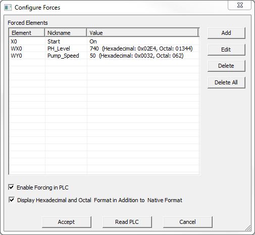
Forced Elements - lists the elements in the force table.
Element - the I/O point or memory element being forced.
Nickname - the element's nickname (if present).
Value - the constant value (or symbolic constant) the element is being forced to.
Add - invokes the Add Force dialog to add a new I/O point or memory element in the force table (see below).
Edit - invokes the Edit Force dialog to change the constant value for an I/O point or memory element already in the force table (see below).
Delete - removes the currently highlighted I/O point or memory element from the force table.
Delete All - removes all of the I/O points and memory elements from the force table.
Enable Forcing in PLC - When the first entry is added to the force table, this checkbox is automatically checked, and will remain checked as long as entries remain in the force table. Unchecking this box will leave the I/O points and memory elements in the force table but the CPU will not force the entries to their specified constant values.
When there are entries in the force table and Enable Forcing in the PLC is checked, and the CPU is in Run mode, Forces will be displayed in the Status bar. If the CPU is in Program mode, Forces Suspended will be displayed in the Status bar.
Display Hexadecimal and Octal Format in Addition to Native Format - enabling this option will add the hexadecimal and octal representations of the force value to the Value column.
Accept - saves any changes made to the force table to the CPU then closes the Configure Forces dialog.
Read PLC - reads the force table currently stored in the CPU then displays those entries in the Configure Forces dialog.
Cancel - does NOT save any changes made to the force table and closes the Configure Forces dialog.
Adding, Editing, and Deleting Force Table Entries
There are multiple ways to add entries to the force table and delete entries from the force table.
-
Use the Configure Forces dialog itself. Clicking the Add button will open the Add Force dialog which is used to add a new I/O point or memory location and its force value into the force table. Clicking the Edit button will invoke a similar dialog to modify the currently highlighted entry that is already in the force table.
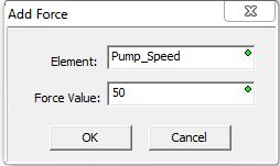
Element - enter the I/O point or memory element to add to the force table. This can be any I/O point or writable memory element (excluding the aforementioned elements) in the CPU.
Force Value - the force value depends on the data type of the element as follows:
For Discrete I/O points and BIT-sized memory elements this field presents the option of OFF or ON.
For Analog I/O points and numeric memory elements (Byte, Word, DWord, and Real), this field allows entry of any constant value or any symbolic constant.
Click OK to add / remove the Element and its value to / from the force table or Cancel to exit without adding / removing the Element and its value to / from the force table.
-
In a Ladder View, right-click on the element in the Ladder diagram and select Force Element... to add that element to the force table, or select Unforce Element... to remove that element from the force table (if it exists in the force table). This method will open the Force Element dialog with the Element field prefilled, and will prompt the user for the Force Value. The force value depends on the data type of the element as follows:
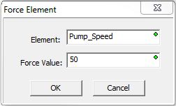
For Discrete I/O points and BIT-sized memory elements this field presents the option of OFF or ON.
For Analog I/O points and numeric memory elements (Byte, Word, DWord, and Real), this field allows entry of any constant value or any symbolic constant.
Click OK to add / remove the Element and its value to / from the force table or Cancel to exit without adding / removing the Element and its value to / from the force table.
-
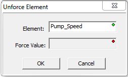
In a Data View, right-click on the element in the list and select Force Element... to add that element to the force table, or select Unforce Element... to remove that element from the force table (if it exists in the force table). This method will open the Unforce Element dialog with the Element field prefilled with the Element to remove from the force table. No value can be entered in the Force Value field.
Click OK to add / remove the Element and its value to / from the force table or Cancel to exit without adding / removing the Element and its value to / from the force table.
How Forced Elements are Displayed in a Ladder View
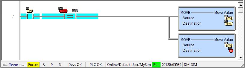
I/O points and memory elements that are being forced will be displayed with a red background. In the image below, D10 is being forced to a value of 999 (which will allow power flow to the two MOVE instructions). In the second MOVE instruction, the memory location D3 is being forced to a value of 0.
Notice the Forces indicator in the Status bar while the CPU is in Run mode.
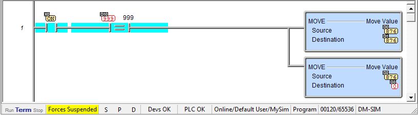
If the force table has entries, and Enable Forcing in PLC is checked. but the CPU is in Program mode, the elements that are being forced will be displayed in red with a white background. In the image below, D10 is being forced to a value of 999 (which will allow power flow to the two MOVE instructions). In the second MOVE instruction, the memory location D3 is being forced to a value of 0.
Notice the Forces Suspended indicator in the Status bar while the CPU is in Program mode.
Forces Still Active Alert on Project Close
If an attempt is made to close the project or disconnect from the CPU with I/O points or memory elements currently being forced, this dialog to be displayed:
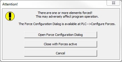
Open Force Configuration Dialog - opens the Configure forces dialog so that entries in the force table can be removed, or the Enable Forcing in PLC option can be unchecked to leave the entries in the table but stop forcing the entries to their constant values.
Close with Forces active - disconnects from the CPU, leaving the force table intact and force table processing in place.
Cancel - close the Attention! dialog and the programming session remains online
See Also:
Using
the Trend View to Monitor the Do-more CPU
Using
the Data View to Monitor Do-more CPU Memory