Topic: DMD0488

HWCONFIG - Configure Hardware
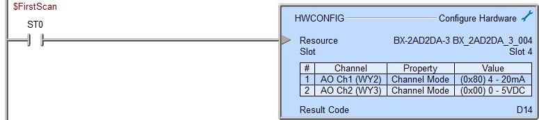
When the PLC system powers up, the Module Configurations are read from the PLC's ROM and a copy is placed into the PLC's RAM. The Configure Hardware (HWCONFIG) instruction is used to alter the values that were placed in the RAM copy of the Module Configurations at power up - this instruction does not change the values stored in the System Configuration in ROM, it only changes the values in the PLC's RAM copy.
Note: changes made by this instruction are maintained through Program -to- RUN mode changes, but are NOT maintained through a power cycle.
This instruction can make runtime changes to some of the configuration parameters of the BRX on-board I/O, BRX Universal Analog Modules, BRX Universal Temperature Input modules, and BRX High-Speed I/O modules that reside in the local base. This instruction will not work on those same modules if they reside in Ethernet Remote I/O slave systems.
Parameters:
Note: Use the F9 key or click the 'three dot box' at the right edge of the parameter field to open the Default Element Selection Tool (the Element Picker or the Element Browser) or use the Down-Arrow key (Auto-Complete) on any parameter field to see a complete list of the memory locations that are valid for that parameter of the instruction.
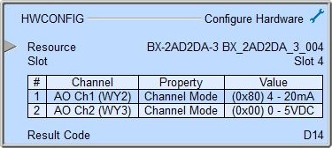
Resource will contain a list of the hardware devices on the system that have configuration parameters that can be changed by this instruction. Entries in the list will contain the part number and module configuration name (if applicable). Only one resource can be selected
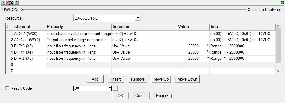
Next is the Table of Properties that will be changed for the selected Resource. Each row in the Table contains the following:
Channel selects the discrete I/O point, analog channel, or global set properties to be configured.
Property selects the configurable aspect of the Channel.
Selection is the new parameter value for that Property from a list of known valid options.
Value is the user-supplied parameter value when one can't be selected from a list.
Info is additional text description of the Selection and / or Value options.
Note: it is highly recommended that all of the parameters for a single Resource be configured in the same HWCONFIG instruction.
The buttons below the Resource table provide functions to organize the rows in the table: Add opens the row editor sub-dialog so that a new entry can be added to the end of the table. Insert inserts an empty row before the currently selected row / Edit opens the currently selected row in the row editor sub-dialog / Remove deletes the currently selected row. Move Up / Move Downmoves the currently selected row up one row or down one row respectively.
Selected Resource
Part Numbers Affected
Configuration Parameters That Can Be Changed
BRX MPU On-board I/O
BX-DM1-10x
BX-DM1E-10x
BX-DM1-18x
BX-DM1E-18x
BX-DM1-36x
BX-DM1E-36x
BRX Universal Analog Modules
BX-04AD-3
BX-08AD-3
BX-2AD2DA-3
BX-4AD4DA-3
Analog Input Type and Range
Analog Input Filter Time
Analog Output Range
BRX Universal Temperature Modules
BX-04UT
BX-08UT
BX-4UT4DA-3
BX-4UT4TD1
BX-4UT4TD2
BX-4UT4TR
Temperature Input Probe Type
Temperature Input Filter Time
BRX High-Speed I/O Modules
Discrete Input Filter Time
Result Code is the value returned by the configuration process. A value of 0 indicates there is No Error. One or more of the following Bits can be ON to indicate an error occurred:
Bit 0 ON : Value Out of Range
Bit 1 ON : Invalid Channel Specified
Bit 2 ON : Unknown Property
If the I/O configuration of the system changes so that the selected Resource is no longer available, for example: an I/O module was removed or the I/O modules were rearranged, the following dialog will be displayed:
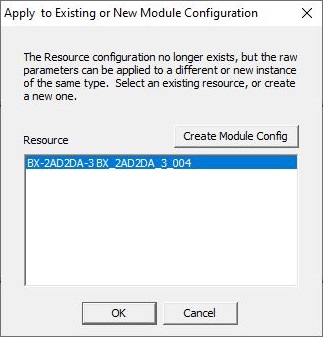
If there is a Module configuration in the system that is compatible with the selected Resource - most likely the condition if the I/O modules were rearranged in the base - that Module configuration can be selected from the list and the editor for the HWCONFIG instruction will open so that the existing Channel parameters can be applied to the new Resource.
If a compatible Module configuration does not exist - most likely the condition if an I/O Module was added to the system - click the Create Module Config button to open the Module Configuration utility of the System Configuration where the new module can be configured.
Status Display:
The gray triangle at the right end of an input leg indicates the input is edge triggered, meaning that each time the input logic transitions from OFF to ON the instruction will run one time to completion.
See Also:
DEVREAD - Read Device Register
DEVWRITE - Write Device Register
RD - Read From Intelligent Module
WT - Write To Intelligent Module
Related Topics:
DATAINFO - Query Information about Data Memory
HWINFO - Get Hardware Information
Rung Example: