Topic: DMD0064

OPENDEV - Open Device
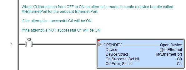
The Open Device (OPENDEV) instruction is used to create a logical reference to a physical Device, then prepare the target device for access by other instructions that will use this device reference. This allows a Do-more project to be written using a logical Device which can be changed at runtime. An example of how this instruction can be used is found in the Do-more Simulator examples named BatchData1.Dmd. The project generates a report that can be sent to the User Log or to the Do-more Logger. Instead of generating two code-blocks that are identical except for where the report is sent. a Device Reference for the destination is created that can be changed at runtime to point to either the User Log or the Do-more Logger.
Parameters:
Note: Use the F9 key or click the 'three dot box' at the right edge of the parameter field to open the Default Element Selection Tool (the Element Picker or the Element Browser) or use the Down-Arrow key (Auto-Complete) on any parameter field to see a complete list of the memory locations that are valid for that parameter of the instruction.
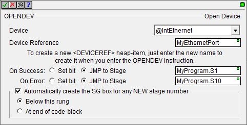
Device - selects which device to create the device reference for.
No devices available - indicates there is no device that is appropriate for this instruction. Select one of the following to create the required device:
create device - select this option to open the Device Configuration dialog of the System Configuration to create a new device of the appropriate type.
create module - select this option to open the Module Configuration dialog of the System Configuration to create a new module configuration that can provide a device of the appropriate type.
Device Struct - the device reference
structure that will contain the reference to the opened hard device. 1
to 16 alphanumeric character name. Device Struct names must follow Nickname Rules![]() Nicknames can be 1 to 16 characters in length and consist of any combination of alphanumeric characters and underscores ('_', 'a-z', 'A-Z', 0-9), no spaces or punctuation marks are allowed, and must begin with a letter or an underscore..
Nicknames can be 1 to 16 characters in length and consist of any combination of alphanumeric characters and underscores ('_', 'a-z', 'A-Z', 0-9), no spaces or punctuation marks are allowed, and must begin with a letter or an underscore..
The On Success and On Error parameters specify what action to perform when this instruction completes. You do not have to use the same type of selection for both On Success and On Error.
If the Set Bit selection is used for either On Success or On Error, the specified BIT location will be SET OFF when the instruction is first enabled and will remain OFF until the instruction completes. Once complete, the appropriate Success or Error bit location ON. The specified Bit location is enabled with a SET (Latch) operation meaning that it will remain ON even if the input logic for the instruction goes OFF.
If the JMP to Stage selection is used for either On Success or On Error the target Stage must be in the same Program code-block as this instruction, you cannot specify a target Stage that exists in a different Program code-block. When the operation finishes, the target Stage will be enabled the same way as a standalone Jump to Stage (JMP) instruction would do it. The JMP to Stage option will only be available if this instruction is placed in a Program code-block.
On Success selects which of the following actions to perform if the operation is successful:
- Enable SET Bit then specify any writable bit location.
- Enable JMP to Stage then specify any
Stage number from S0 to S127 in the current Program code-block.
On Error selects which of
the following actions to perform if the operation is unsuccessful:
- Enable SET Bit then specify writable bit location.
- Enable JMP to Stage then specify any Stage number from S0 to S127 in the current Program code-block.
If either the On Success or On Error selections are set to JMP to Stage, Automatically create the SG box for any NEW stage number will be enabled which will automatically create any target stage that does not already exist.
- Below this rung will create the new target stage on a new rung following this instruction.
- At end of code-block will create the new target stage as the last rung of this Program.
Creating a new Device Reference requires a change to the Memory Configuration (notice the yellow indicator next to the Device Struct that will be created). This confirmation dialog makes sure that the pending change is what the programmer intends.
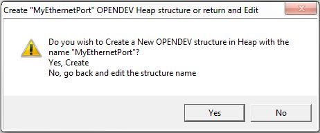
Click the Yes button to continue, this will create the new Device Reference Struct in Heap memory; click the No button to go back to the Open Device instruction editor.
Structure Memory:
After the Open Device (OPENDEV) instruction completes the Memory Configuration will contain a new Device Structure. It can be viewed in the Project Browser at: Configuration -> Memory -> User -> Structures -> DEVICEREF tree. There will be an entry for each Device Structure, each structure will contain the following read-only fields:
.DeviceID - a system-generated, unique, reference number that is associated with the hard device that was opened.
.Open - will be ON if the target device is ready to be used in other relevant device instructions, that is, it is OPEN.
.Success - reflects the sate of the Success bit in the most recently executed device instruction.
.Error - reflects the sate of the Error bit in the most recently executed device instruction.
Status Display:
A successfully opened device will display the hard device name (@xxx) next to the Device Struct.
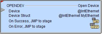
An unopened device will display 'Null Device' next to the Device Struct.
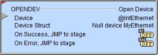
The red triangle in the upper left corner of the status display indicates this is a Fully Asynchronous instruction.
The gray triangle at the right end of the input leg indicates the input is edge-triggered, meaning the instruction will execute each time the input logic transitions from OFF to ON.
See Also:
OPENDEV - Open Device
DEVREAD - Read Device Register
DEVWRITE - Write Device Register
Related Topics:
For more information on Devices, Device References, and how to configure them go to the Device Configuration section of the System Configuration.
Example Using Stages:
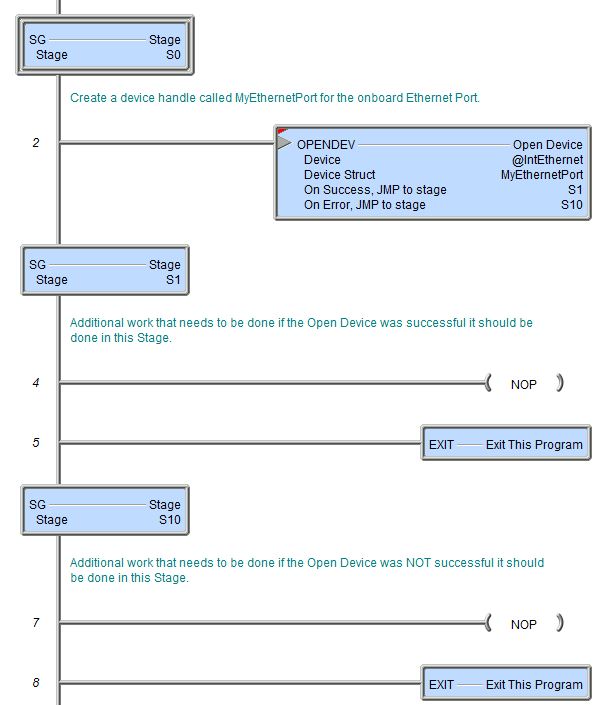
Rung Example: