Topic: DMD0392
FILELOG - Log to File
The Log to File (FILELOG instruction is automatically store a copy of the current value of PLC data points in a file on one of the file systems. The FILELOG instruction can be configured to operate one for two modes:
When configured for Log on Event Mode the current values of the specified Elements will be written to the Log file each time the input logic (the Event) transitions from OFF to ON. This is the proper configuration to log data for events that happen at irregular intervals. A good example is a Alarm condition where you need to a snapshot of the data points concerning that Alarm.
When configured for Timed Mode, when the instruction is first enabled and while the instruction maintains power flow, the instruction will use the system clock to log the current values for the specified Elements at a recurring time interval. This is the proper configuration to use when you need to sample a collection of data points at a prescribed interval for a period of time. A good example is mimicking the behavior of a chart recorder.
The Log to File instruction always works in create / append mode. If the Log File does not exist it will be created and the new data will be written to the file. If the Log File does exist the new data will be appended to the existing contents of the file. Choosing the option to Append Time Stamp to File Name to the Base File Name will generate a new filename each time the selected interval expires.
Note: the current Time and Date are automatically added as the first two fields of each new record when it is added to the Log File; you DO NOT need to add manually the Time and Date to the Element List to get a Time stamp in each record.

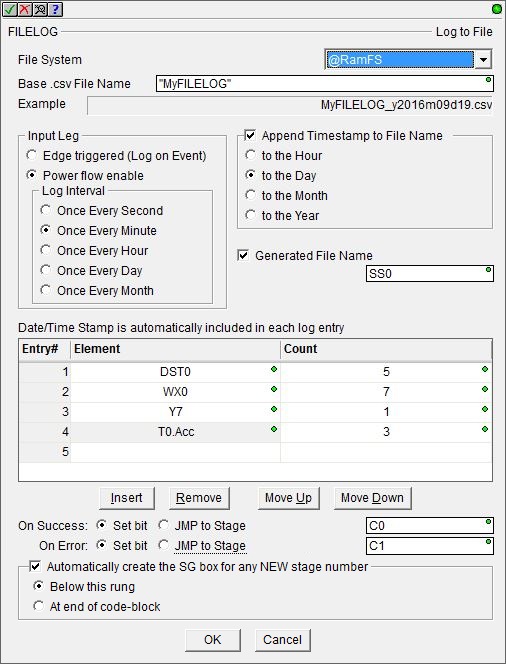
File System selects which of the available file systems to use:
@RamFS is the 1 MB file system in the Do-more CPU's system RAM. All Do-more CPUs will have this file system available.
@SDCardFS is the file system on the removable media installed in the micro-SD card slot (BRX only). This file system is automatically created when the removable media is inserted into the micro-SD card slot. The $SDCardFS.MediaInstalled and $SDCardFS.MediaMounted structure elements will be ON if there is a functional file system available on media in the micro-SD slot.
Note: All micro-SD media must be formatted in a PC before it can be used in a Do-more CPU. Only micro-SD media which has been formatted as FAT32 is supported. The file system can only access the first 32GB of storage space on the micro-SD media; any micro-SD card that is larger than 32GB must be reformatted to FAT32 before it can be used.
The Base .CSV File Name is the full path (including any directories) of the file to use for logging on the selected file system. The file extension ".csv" will automatically be added to the Base File Name so, you should not enter a file extension as part of the base file name. This can be any text enclosed in double quotes, or any system or user-defined string.
Input Leg selects how the instruction is enabled.
- Edge Triggered (log on Event) means each time the input leg logic transitions from OFF to ON a log entry for each Element is appended to the Log file.
- Power flow Enabled means that each time the input logic transitions from OFF to ON a log entry for each Element is written to the Log file, then, if the input logic remains ON, each time the selected Log Interval in the system clock expires, a new entry for each Element is appended to the Log file at the selected interval:
For example: if the current time is 8:15 AM and the Log Interval is set to Once Every Hour, when the FILELOG is enable, you will get a log file entry for 8:15 AM, the next log file entry will be 45 minutes later at 9:00 AM, then subsequent log file entries will occur 10:00 AM, 11:00 AM, etc.
Enable the Append Time-stamp to Base File Name option to automatically append some or all of the Date and Time to the Base CSV File Name when it is created.
Enable the Generated File Name option and specify a String element to have the FILELOG instruction place a copy of the name of the current log file being used. If the file name is being manually constructed at runtime, this can be useful when verifying the filename is being built correctly.
Note: Because the Do-more file system supports long file names, any time the filename is longer that 8 characters in the name plus 3 characters in the file extension, the entry in the FAT (file allocation table) for this file will use the long file name format. This format will get the required additional space for the file name from the FAT. The result of using long file names is there wont be space in the FAT for the full complement of files and folders. The exact number of files and folders that can be created in a folder is largely dependent on how long the file and folder names are.
What this means with regard to this option is that if it's enabled , you will not be able to get the maximum number of files and folders per directory. The maximum number of files you can expect in a single folder is dependent on how long the Base CSV File Name is and how much of the time stamp you choose to automatically append. The selections that follow vary how much of the Date and Time to append to the Base CSV File Name. The table estimates how many log files of that filename length you can expect to be able to create in a folder. The Example field will update dynamically as the selection is made so that you can verify the Log file name is what you expect.
List of Elements to Log is the list of memory Elements that will be written to the log file each time the instruction runs. The list can contain up to 50 Entries. An Entry can be any Element or range of Elements in the CPU. The total amount of data per Log to File instruction cannot exceed 1024 bytes. As stated earlier: the current Time and Date are automatically added to each new record that gets appended to the Log File; you DO NOT need to manually add the Time and Date to the Element List to get a Time stamp in each record.
Note: Use the F9 key or click the 'three dot box' at the right edge of the parameter field to open the Default Element Selection Tool (the Element Picker or the Element Browser) or use the Down-Arrow key (Auto-Complete) on any parameter field to see a complete list of the memory locations that are valid for that parameter of the instruction.
Entry # is the order the Elements will appear in the Log file.
Element is the single Element or first Element in a range whose value will be written to the Log file. This can be any valid Bit or Numeric element, structure field, or String.
Note: if the element is a Real (floating point) value, the default formatting will add one zero to the left of the decimal so you are assured of getting at least "0" written to the log file for this element. If the Real value is very small (less than 0.0001) or very large (greater than 4 digits) it will be displayed in scientific notation (e.g. 0.00001 will be stored in the file as 1E-005 and 123456.0 will be displayed as 1.24E+004).
To change the number of leading zeros, the number of digits to the left and right of the decimal point, or the display format of the stored value, you will need to use the FmtReal() function in a STRING, then use that String here as the element instead of the Real element itself.
Count is the number of consecutive Elements to write to the Log file. The maximum number of Elements in a single range is 10.
The order that the elements will be written to the Log file is determined by the order in this list of elements. The following four buttons are used to help manage that ordering:
Insert will insert an entry row above the current cursor position.
Remove will delete the contents of the currently selected row.
Each press of Move Up or Move Down will move the currently selected row up one position toward the top of the table or down one position toward the bottom of the table respectively.
The On Success and On Error parameters specify what action to perform when this instruction completes. You do not have to use the same type of selection for both On Success and On Error.
If the Set Bit selection is used for either On Success or On Error, the specified BIT location will be SET OFF when the instruction is first enabled and will remain OFF until the instruction completes. Once complete, the appropriate Success or Error bit location will be set ON. The specified Bit location is enabled with a SET (Latch) operation (not an OUT operation) meaning that it will remain ON even if this instruction's input logic goes OFF.
If the JMP to Stage selection is used for either On Success or On Error the target Stage must be in the same Program code-block as this instruction, you cannot specify a target Stage that exists in a different Program code-block. When the operation finishes, the target Stage will be enabled the same way as a standalone Jump to Stage (JMP) instruction would do it. The JMP to Stage option will only be selectable if this instruction is placed in a Program code-block.
On Success selects which of the following actions to perform if the operation is successful:
- Enable Set Bit then specify any writable bit location.
- Enable JMP to Stage then specify
any Stage number from S0 to S127 in the current Program code-block.
On Error selects which of
the following actions to perform if the operation is unsuccessful:
- Enable SET Bit then specify writable bit location.
- Enable JMP
to Stage then specify any Stage number
from S0 to S127 in the current Program code-block.
If either the On Success or On Error selections are set to JMP to Stage, Automatically create the SG box for any NEW stage number will be enabled which will automatically create any target stage that does not already exist.
- Below this rung will create the new target stage on a new rung following this instruction.
- At end of code-block will create the new target stage on the last rung of this Program.
If the Log to File instruction is configured for Timed Mode, the On Success and On Error parameters will be processed when the instruction is first enabled and each time a new entry is written to the log file.
Error Codes
Improper use of any FILE instruction or any file system hardware problem will generate a warning message at runtime. When any of these warnings are generated, the On Error parameter in the instruction will be ON and the System ERR variable will contain one of the following text messages. You will also be alerted to this condition by yellow "Warning" text displayed in the Status Bar of Do-more Designer. Clicking that text will open the System Status to display the full text of the warning message.
Status Display
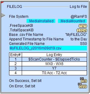
Configured to Log on Event
|
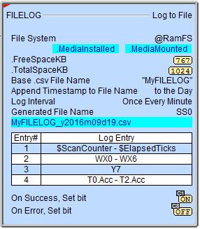
Configured to Log at a Timed Interval
|
The red triangle in the upper left corner of the status display indicates this is a Fully Asynchronous instruction.
The gray triangle at the right end of the input leg indicates the input is edge-triggered, meaning this instruction will execute each time the input logic transitions from OFF to ON.
MediaInstalled / MediaMounted / FreeSpaceKB / TotalSpaceKB - the current values of these numeric fields from File System's associated structure.
Sample Output
The following shows a sample of a file generated by FILELOG instruction that adds an entry for DST0 through DST4, D0, D1, X2 and X3 at one hour intervals. Notice the column headers contain Nicknames for memory locations that have them.

See Also
FILELOG - Log to File
FILEQUERY - Query File or Folder Information
FILESEEK - Seek to Position in File
FILESYSCMD - Perform File System Command
EMAIL - Send Email (with file attachment)
Related Topics
Example #1
Examples of using the different methods to trigger the execution of the FILELOG instruction.

Example #2
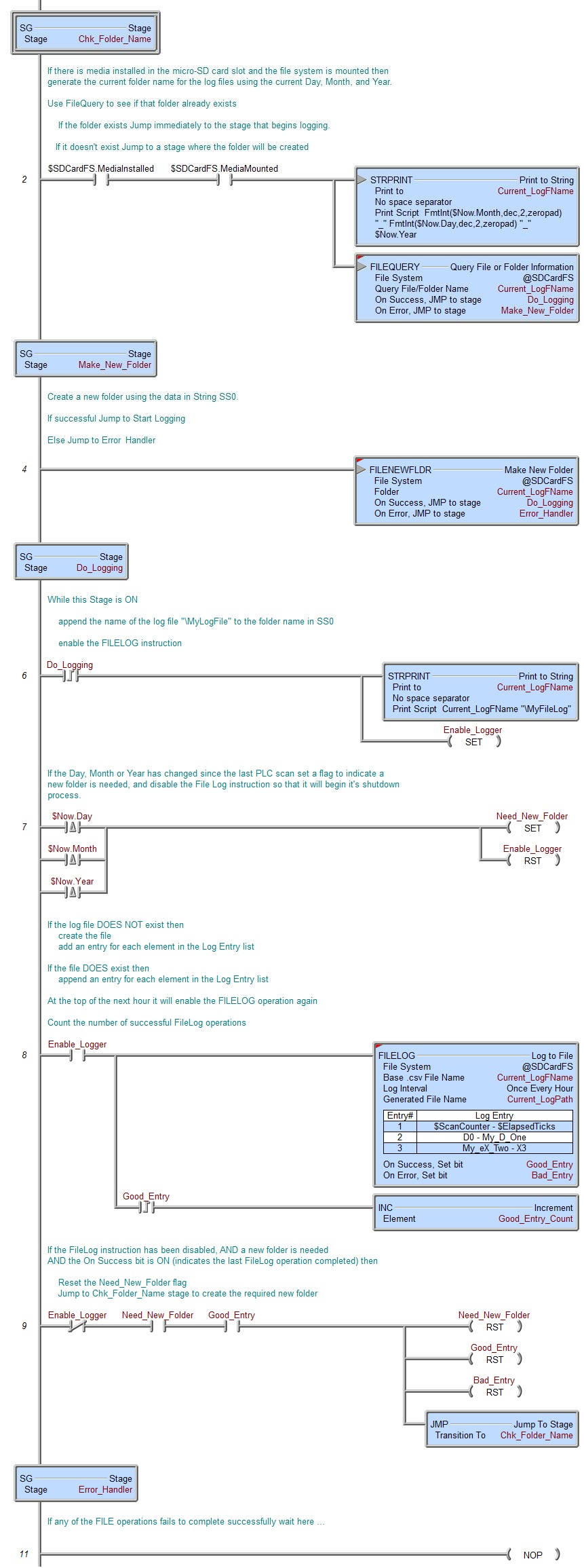
Automatically create folders named for the Month_Day_Year and store the log files created during each Month_Day_Year in the appropriate folder.


