Topic: DMD0502

Stage Programming Concepts
Traditional ladder logic programming is very good at controlling applications
with concurrent processes, but it has some clear disadvantages when dealing
with controlling applications that are sequential in nature, or applications
that have event-driven sequences. And while it’s true that traditional
ladder logic programming can be made to provide for controlling sequential
operations, doing so can result in one or more of the following:
Programs that contain so many interlocking relays that it becomes tedious to understand and maintain.
When debugging processes that are ”stuck”, it can be difficult to find the rung where the error occurred.
Programs become difficult to modify because they do not intuitively resemble the application problem they are solving.
A few moments of studying the stage programming concept is one of the greatest investments in programming speed and efficiency a PLC programmer can make. To that end, this chapter is designed as a self paced tutorial on stage programming. So for the best results, start at the beginning and do not skip over any sections. Study each stage programming concept by working through each of the examples as they build progressively on each other.
State Transition Diagrams
Sometimes it is helpful to step back from how a PLC is used to solve control problems and focus only on the devices, the states, and the events of the control process that needs to be solved. Clear thinking and concise analysis of an application without worrying about details of how the control solution will be implemented gives the best chance at writing efficient, bug free programs. This is where state transition diagrams work very well.
State transition diagrams express a process control problem independently of the programming language that will be used to implement the solution. So before we describe stage programming in detail, some understanding of how to use state transition diagrams to arrive at these process states and the transition events that move the process between these states is in order.
State transitions diagrams are tools that help draw a picture of the control process. These diagrams define the objects in the system. These diagrams then describe the behavior of the system in terms of the possible states of these objects as events occur. Get the objects and behaviors of the process right and the stage program will also be right.
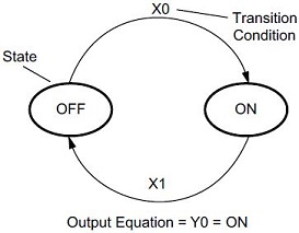
Most manufacturing processes consist of a series of activities or conditions, each lasting for several seconds, minutes, or even hours. We can call these ”process states”, and these process states are either active or inactive at any particular time. On the diagram to the right, the process states are represented by ovals with the state name inside.
Also involved are defining the actions or events, called ”transitions”, that will move the control process through these process states in the desired sequence. In the diagram to the right the transitions are represented as lines with arrows, and the transition event name labeling the lines.
It is outside the scope of this document to teach a course in state transition diagramming. A good refresher course about creating these diagrams and using them to describe a process can be found on Wikipedia at http://en.wikipedia.org/wiki/State_transition_diagram.
Using Stage Programming to Implement State Transition Diagrams
Stage programming involves organizing the ladder logic program into sections, called stages, each of which represents one of the aforementioned process states. Also involved is organizing the transition events to move the process through the desired sequence of stages. Now the stage programming instructions that will be used to implement a state transition diagram can be discussed, and some of the details of using stage programming in the Do-more PLC can be addressed.
Stage Numbering
Each Program code block can have up to 128 Stages (SG), which are numbered S0 through S127.
Stages within a Program code block do not have to be numbered sequentially, and you can skip stage numbers. The stage number is simply an identifier, it does NOT imply sequence or order.
There cannot be duplicate stage numbers in the same Program code block.
Stage (SG) instructions cannot be in a Task code block, they can only be in a Program code block.
Initial Stages
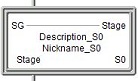
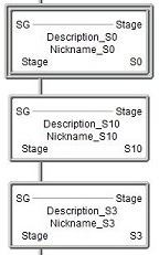
The Stage (SG) instruction that is physically the first stage in each Program code block is called the Initial Stage, and it will be automatically enabled each time the Program code block is run. The Initial Stage has a double box border which will visibly distinguish it from the other stages in the Program code block. Other than being automatically enabled each time a Program code block is run, the Initial Stage operates just like a regular stage.
Enabling Stages
To allow the Do-more PLC to process the instructions within a stage, that stage must be 'enabled'. Enabled means the ladder logic rungs within that stage are processed as part of the current controller scan; disabled means the ladder logic rungs within that stage are NOT processed as part of the current controller scan.
Stages are individually enabled and disabled. Stages can only be enabled
through one of the following three methods:
-
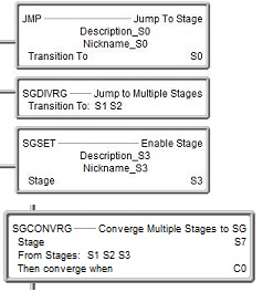
a "Jump" operation when the stage is the target of a Jump to Stage (JMP) or a Jump to Multiple Stages (SGDIVRG) instruction.
-
a "Stage Set" operation when the stage is the target of a Stage Set (SGSET) instruction.
-
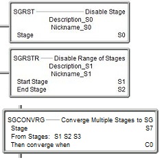
a "Converge" operation when the stage is the target of a Converge Multiple Stages to SG (SGCONVRG) instruction (e.g. "S7" in the picture).
Disabling Stages
Once a stage is enabled, it will remain enabled until is specifically
disabled by one of the following methods:
-
the stage is the source of a Jump to Stage (JMP) or Jump to Multiple Stages (SGDIVRG) instruction, that is, "Jumping" out of stage will disable that stage.
-
the stage is the target of a Disable Stage (SGRST) or Disable Range of Stages (SGRSTR) instruction.
-
the stage is the source of a Converge Multiple Stages to SG (SGCONVRG) instruction (e.g. "S1" or "S2" or "S3" in the picture).
Stage Bits
Each stage has an associated status bit that reflects whether that stage is enabled or disabled. The ladder logic in a Program code block can read the stage bits from other Program code blocks, but they cannot write to the stage bits of other Program code blocks. This allows Program code blocks to be aware of the status of stages in other Program code blocks and the Program code blocks can then be synchronized (interlocked) if needed.
Since a Program code block can have a maximum of 128 stages, there are 128 stage bits per Program code block. The stage bits for a particular Program code block are referenced in the form <program-code-block name>.<stage number>. For example, stages in the $Main Program code block are referenced as $Main.S0 through $Main.S127.
Stage bits are contained within the scope of the Program code block, meaning that each Program code block has stage bits named <program-code-block name>.S0 through <program-code-block name>.S127.
Note: Because stage names are contained within the scope of the Program code block, the stage names will be displayed in the instructions using only the stage number. To display the fully qualified stage name, that is, <program-code-block name>.<stage number>, in the instructions, go to the Ladder tab of the View -> Options menu and uncheck the "Abbreviate Stage Names (Use S0 over $Main.S0)" option. Stage status bits from other Program code blocks will always be displayed in the fully qualified form.
At this point, The best way to proceed is to solve some common control applications by walking through the process of developing the state transition diagrams then using them to create stage programs. Again, it’s important to follow along through each example program as the information builds from one to the next.
Special Considerations
Some instructions operate in specific ways when placed inside of a Stage. This is especially important to those familiar with Stage programming in the DirectLOGIC line of PLCs who should be aware of how instructions with the same name work in Do-more CPUs differently from how they work in DL CPUs.
Any instruction that has an edge-triggered input requires that the input be OFF then turn ON during a subsequent scan. If these instructions are contained within a Stage - AND - the input logic is ON when the Stage is first enabled, the edge triggered input will execute. This happens because the instruction internally stores the state of the input from the previous scan - which will be OFF because the Stage is disabled - and the first scan when the Stage is enabled is also the scan where the input logic is ON, so the edge trigger's OFF to ON requirement is met and the instruction will execute. Those familiar with Stage implementation in DirectLOGIC CPUs will notice that this is different, DirectLOGIC CPUs required the Stage be enabled AND then the input then be OFF and then be ON, which took a minimum of two scans to make the edge triggered inputs execute.
The only exceptions to this rule are the Counter instructions Up Counter (CNT), Down Counter (CNTDN), Up / Down Counter (UDC) , Global Up / Down Counter (UDCG). The Do-more CPU has special processing to prevent these Counter instructions from inadvertently counting if the input is logic is ON when the Stage is first enabled.
Using the Same Program Elements in Multiple Stages
Those familiar with Stage programming in DirectLOGIC will be familiar with referencing the same memory element in multiple Stages, a prime example is using the same Timer in multiple Stages, and as long as only one of those Stages is active on any given scans it works perfectly fine. The same is true in Stage programming in Do-more CPUs but I would caution you against doing for the simple reason that the reason it was done in DirectLOGIC CPUs - there's a fixed, small number of Timers - doesn't exist to the same degree in Do-more CPUs. Reusing memory elements can also add confusion for anyone else that looks at the ladder logic at a later date because it's typically not an advised practice in other types of ladder logic programming. Do-more CPUs have much more available memory than DirectLOGIC CPUs, so there are more memeory elements to choose from to begin with, and if you need more, you can extend the default ranges or even add additional ranges of elements.
Stage Programming Concepts
Example 1 - A Simple 2-State Process
Example 2 - A Lamp On / Off Controller
Example 3 - A Garage Door Opener
Review - Steps to Writing Successful Stage Programs
Stage Programming Instructions
SGRSTR - Disable Range of Stages
SGDIVRG - Jump to Multiple Stages
SGCONVRG - Converge Multiple Stages to SG