Topic: DMD0503

Example 1 - A Simple 2-State Process
Consider a simple process which controls an industrial motor.
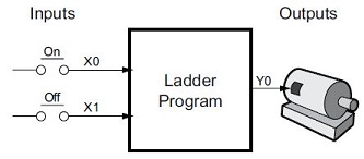
The process will use one momentary push button to turn the motor on, and a second momentary switch to turn it off. The machine operator will press the appropriate push button for a second or so. From this description it’s easy to see that there two states of the process: ON and OFF.
The next step is to draw a state transition diagram
that represents this process. This diagram shows the two states OFF and
ON, with two transition lines between the states.
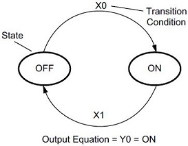
When the process is in the OFF state, and the event X0 is true, the process
will transition from OFF to ON.
When the process is in the ON state, and the event X1 is true, the process
will transition from ON to OFF.
The output of our process controller is Y0, which is true any time we are
in the ON state.
To help see the relationship between the two methods in problem solving, first look at the state diagram implemented first as a traditional ladder logic program, then implemented as a stage program.
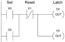
The ladder logic solution shown consists of the two inputs (X0 and X1) a self-latching control relay, C0, and the output (Y0).
When the On momentary push button (X0) is pressed, output coil C0 turns on and the C0 contact on the second row latches itself on. So, X0 sets the latch C0 on, and it remains on after the X0 contact opens. The motor output Y0 also has power flow, so the motor is now on.
When the Off push button (X1) is pressed, it opens the normally closed X1 contact, which resets the latch. Motor output Y0 turns off when the latch coil C0 goes off.
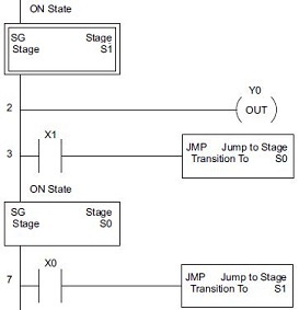
The stage programming solution is shown below. The two Stage instructions S0 and S1 correspond to the two states OFF and ON. In the ladder rungs below, each stage box belongs to its respective stage. Recall that the PLC only scans the rungs in a stage when the stage is active.
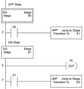
Assume the process begins in the OFF State, meaning only Stage S0 is enabled, meaning only Rung 2 is executed and Rungs 6 & 7 are not.
When the On push button (X0) is pressed, a stage transition occurs. The Jump to Stage (JMP) S1 instruction executes, which disables Stage S0 and enables Stage S1. Since Stage S1 follows after Stage S0 in the logic of this example, it will be executed on this same scan.
On the next PLC scan, the CPU will not execute Stage S0, but will execute stage S1.
In the On State (Stage S1), the unconditional output Y0 turns the motor on.
When the Off push button (X1) is pressed, a transition back to the Off State occurs. The Jump to Stage (JMP) S0 instruction executes, which disables Stage S1 and enables Stage S0.
On the next PLC scan, the CPU will execute Stage S0 and will not execute Stage S1, so the motor output Y0 will turn off.
The Off state (Stage S0) will be ready for the next cycle.
At first the advantage to Stage Programming might not be obvious; in fact, the stage program is actually longer than the ladder logic program. But, as control problems grow in complexity, stage programming will quickly out-perform traditional ladder logic programming methods in simplicity, program size, execution speed, etc.
Initial Stages
As mentioned earlier, at power-up and during Program mode -to- Run mode transitions, the PLC will always begin by disabling all of the stages in all of the Program code blocks. Then, each time a Program code block is run, the stage that is located first in a program code block (regardless of the stage number) will be automatically enabled. This stage is referred to as the Initial Stage, and is visually distinguished by a double box border. Aside from being automatically enabled when the Program code block is run, the Initial Stage works like any other stage.
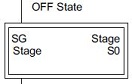
To begin our process control in the OFF state (with the motor off) similarly to how the ladder logic program works, no modifications to the Program code block are required. The PLC will scan contact X0 after power-up, because stage S0 is enabled automatically because it is the Initial Stage.
Both programs can be changed so that the motor is ON at power-up.
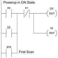
In the ladder logic version of the program above, add the first scan relay (ST0) to the rung so that it will also latch C0 on.
In the stage programming version shown above, the order of the stages needs to be inverted in the program. Stage S1 and its contents must be moved so that it is now the first stage in the Program code block. Notice that the stages were not renumbered, it’s simply the placement within the program that determines which stage is the Initial Stage.
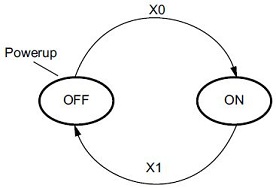
For completeness, the state transition diagram can have the desired power-up state designated as shown, which helps to remind the programmer which stage will be the Initial Stage.
Stage Programming Concepts
Example 1 - A Simple 2-State Process
Example 2 - A Lamp On / Off Controller
Example 3 - A Garage Door Opener
Review - Steps to Writing Successful Stage Programs
Stage Programming Instructions
SGRSTR - Disable Range of Stages
SGDIVRG - Jump to Multiple Stages
SGCONVRG - Converge Multiple Stages to SG