Topic: DMD0505

Example 2 - A Lamp On/Off Controller
This next example will work through a situation common to those new to stage programming, and will illustrate the need for a clear understanding of the different states of the process and the consequences of defining the states incorrectly.
Consider a process where an ordinary momentary push button is used to control a light bulb.

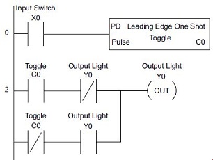
The traditional ladder logic program shown below uses a control relay to latch the switch input so that a push and release cycle will turn the light on, and a subsequent push and release cycle will turn it off. This is traditionally called toggle function.
Next draw the state transition diagram. Note that this example differs from the motor example, because now there is only one push button.
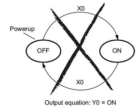
A typical first approach might be to use X0 for both transitions. However, this would not be correct! When the push button is pressed, both transition conditions are met simultaneously. This would cause the control process to continuously transition around the state transition diagram as long as the input condition remains true. When implemented as a stage program this solution would flash the light on or off each scan; definitely not the desired result!
The solution is to make the push and the release of the push button separate events.
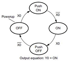
Refer to the new state transition diagram.
At power-up the control process starts in the OFF state.
When the input switch X0 is pressed, the control process will transition to the Push-ON state.
When X0 is released, the control process will transition to the ON state.
When in the ON state, a similar push and release cycle of X0 will take the control process back to the OFF state.
Now there are two unique states (OFF and ON) used when the push button is released, which is what is required to solve the control problem.
The equivalent stage program to implement this is shown below:
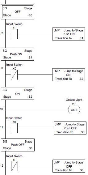
The desired power-up state is OFF, so Stage S0 is the first stage in the program making it the initial stage.
Note that even as the control programs grow more complex, it is still easy to correlate the state transition diagram with the stage program.
Stage Programming Concepts
Example 1 - A Simple 2-State Process
Example 2 - A Lamp On / Off Controller
Example 3 - A Garage Door Opener
Review - Steps to Writing Successful Stage Programs
Stage Programming Instructions
SGRSTR - Disable Range of Stages
SGDIVRG - Jump to Multiple Stages
SGCONVRG - Converge Multiple Stages to SG