Topic: DMD0094

UDCG - Global Up/Down Counter
The Global Up / Down Counter (UDCG) instruction is used to accumulate OFF to ON and ON to OFF state changes of input logic, counting upward from 0 toward an optional preset value and counting downward from a second, optional preset value toward 0. This instruction has the following two ladder logic inputs:
The first input is the UP Count input (UP). Each time this input logic transitions from OFF to ON, the Counter's accumulator will increment by one. If the Up Preset is enabled, the Counter's .Done bit will turn ON when the .Acc value reaches the preset value.
The second input the DN Count input (DN). Each time this input logic transitions from OFF to ON the Counter's accumulator (.Acc) is decremented by one. If the Down Preset is enabled, the Counter's .DnDone bit will turn ON when the .Acc value reaches 0.
Although this is an Up / Down Counter it does NOT have a Reset input leg like the Up / Down Counter (UDC, the Reset Counter (RSTCT) instruction is the proper method to reset this Counter. This is the only Counter that does NOT have termination logic, meaning that it does NOT automatically reset if the Program, Task, or Stage in which the instruction is placed is disabled.
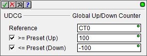
Parameters:
Note: Use the F9 key or click the 'three dot box' at the right edge of the parameter field to open the Default Element Selection Tool (the Element Picker or the Element Browser) or use the Down-Arrow key (Auto-Complete) on any parameter field to see a complete list of the memory locations that are valid for that parameter of the instruction.
Counter Struct specifies which Counter number to edit, and by extension, the name of the Counter's associated structure. This can be any of the System-created Counters, or any user-created Counter. The default Memory Configuration contain 255 predefined Counters named CT0 through CT255.
Optionally enable the >= Preset
and enter the Up Preset count value. The Counter's .Done
BIT will be ON any time the value in the Counter's accumulator
(.Acc) is greater than or equal to the Up Preset value. This can be any 32-bit constant value (-2,147, 483, 648 to 2,147, 483, 647) or any readable numeric
location containing a value in that range.
Optionally enable the <= Preset and enter the Down Preset count value. The Counter's .DnDone BIT will be ON any time the value in the Counter's accumulator (.Acc) is less than or equal to the Down Preset value. This can be any 32-bit constant value (-2,147, 483, 648 to 2,147, 483, 647) or any readable numeric location containing a value in that range.
Termination Scan Behavior:
All Counters - with one exception - have termination logic. This means if the Counter instruction is contained within a Program, a Task, or a Stage, the Counter will automatically be reset any time the containing Program, Task, or Stage stops executing because of an End Program, End Task, or Disable Stage respectively.
The Global Up / Down Counter (UDCG) instruction does NOT have termination logic, meaning that it will retain it's state information even if it is contained within a Program, a Task, or a Stage, that is disabled.
Refer to the Help topic on Termination Behavior for detailed information on the programming elements that have termination logic.
Status Display:
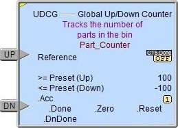
The yellow triangle in the upper left corner indicates this is a Multi-Scan instruction.
The gray triangle to the right of the UP Count input leg indicates this input is edge-triggered, meaning that each time the input logic transitions from OFF to ON the Counter's accumulator will increment by one count.
The gray triangle to the right of the DN Count input leg indicates this input is edge-triggered, meaning that each time the input logic transitions from OFF to ON the Counter's accumulator will decrement by one count.
Counter Structure Members
All Counters have an associated structure with fields that can be used in the ladder program. The structure fields are updated whenever the Counter instruction is processed in the PLC scan. The syntax for using them is <Counter structure>.<field name>, for example: CT1.Acc.
.Acc (read/write) is a 32-bit integer value that represents the current number of counts that have accrued.
.Done (read-only) when counting upward toward a preset value, this Bit will be ON any time the value in the Counter's accumulator (.Acc) is greater than or equal to the Counter's Preset value.
.Reset (read-only) will be ON if the RESET logic is ON, or if the Counter is being held in reset by a Reset Counter (RSTCT) instruction. The Reset input has priority over the UP input, meaning that if the UP input is ON at the same time as the Reset input, the Counter will not count.
.Zero (read-only) will be ON any time the value in the Counter's accumulator value (.Acc) is 0.
.DnDone (read-only) when counting downward toward the down preset value, this Bit will ON any time the value in the Counter's
accumulator value (.Acc) is less than or equal to the Counter's Preset value. This bit field is only used by the Up / Down Counter (UDC) and the Global Up / Down Counter (UDCG) .
See Also:
UDCG - Global Up / Down Counter
Related Topics:
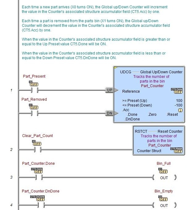
Example: