Topic: DMD0506

Example 3 - A Garage Door Opener
Example 3: A Garage Door Opener
This next stage programming example will create a control solution for a garage door opener. Most readers are already familiar with this application, but the first step is still to describe how the door opener works. This example will start with the basic operation, waiting to add extra features later to demonstrate that stage programs are typically easy to modify.
Process Description
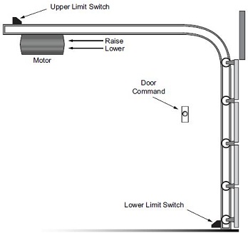
The garage door controller has a motor which raises or lowers the door on command. The garage owner pushes and releases a momentary push button once to raise the door. After the door is up, another push/release cycle will lower the door.
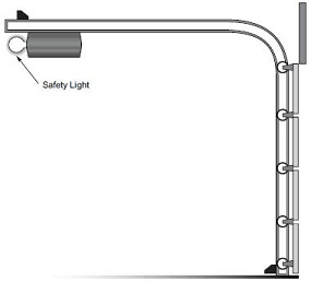
In order to identify the inputs and outputs of the system, it’s sometimes helpful to sketch its main components, as shown in the door side view to the right.
Input & Output Description
The door has an up limit and a down limit switch. Each limit switch closes only when the door has reached the end of travel in the corresponding direction. Neither limit switch is closed while the door is traveling.
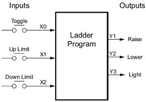
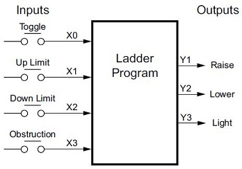
The motor has two command outputs: raise and lower. When neither output is active, the motor is stopped. The door command is a simple push button. If there were more than one input to control the door - whether wall-mounted as shown, or a radio remote control - all of the door control inputs would be logically OR’d together as one switch contact. Refer to the block diagram of the controller shown below:
The Basic Open & Close Functionality
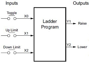
Input X0 is from the push button door control.
Input X1 energizes when the door reaches the full up position.
Input X2 energizes when the door reaches the full down position.
When the door is positioned between fully up or down, both limit switches are open.
The controller has two outputs to drive the motor: Y0 is the up (raise the door) command, and Y1 is the down (lower the door) command.
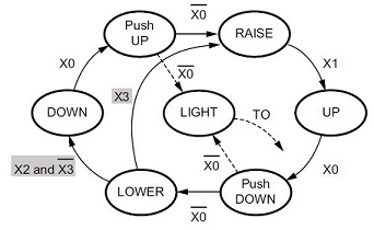
The next step is to draw the state transition diagram. As in the previous Lamp On/Off Controller example, this application also has only one switch for the command input. Refer to the figure below:
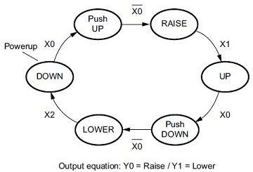
When the door is down (DOWN state), nothing happens until X0 energizes. Its push and release transitions through the Push-Up state to the RAISE state, which will turn on output Y0 and cause the motor to raise the door.
The process transitions to the UP state when the up limit switch (X1) energizes, and turns off the motor.
Then nothing happens until another X0 press-release cycle occurs. That transitions through the Push-Down state to the LOWER state, which will turn on output Y1 to cause the motor to lower the door.
The process transitions back to the DOWN state when the down limit switch (X2) energizes.
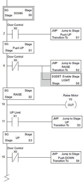
The stage program to implement this state transition diagram is shown below:
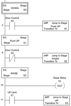
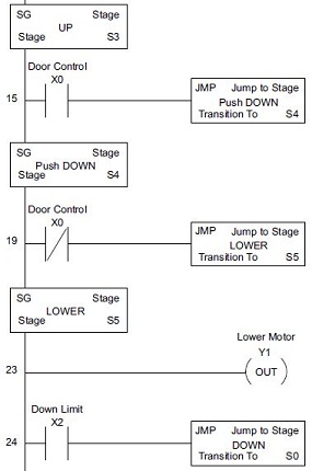
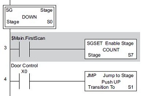
Assuming that the garage door is down at power-up makes the DOWN state the desired power-up state. This is implemented by making stage S0 the first stage in the program. Stage S0 remains active until the door control push button activates, then transitions via a Jump to Stage (JMP) instruction to the Push-UP stage S1.
Releasing the push button X0 then causes a transition through the Push-Up stage S1 to the RAISE stage S2, which will then energize the motor’s raise command output Y0.
When the door reaches the fully-raised position, the up limit switch X1 activates. This transitions the control process to the UP Stage S3, where it waits until another door control command is received.
In the UP stage S3, a push-release cycle of the push button will transition the control process through the Push-Down stage S4 to the LOWER stage S5, where output Y1 is then activated to command the motor to lower the door. This continues until the door reaches the down limit switch, X2.
When X2 closes, the control process transitions from LOWER stage S5 back to the DOWN stage S0, where the control process began.
Note: Notice that stage S0 is the initial stage (it has a double border), so it is automatically enabled at power-up, but afterward it operates like any other stage.
Add a Safety Light Feature
Now that the main function is working, the safety light will be the first feature added to the garage door opener system. Again, start with a written description of the application, then make changes to the state transition diagram as required, and then make the necessary additions and changes to the stage program.
The safety light is a standard feature on most commercially available garage door openers. The light turns on whenever there is any door-open or door-close activity, and then remains on for approximately 3 minutes afterward.
This part of the exercise will introduce the concept of using parallel states in our state transition diagram. Implementation of these parallel stages will be accomplished by using the Enable Stage (SGSET) and Disable Stage (SGRST) instructions.
To control the light bulb, an output Y3 is added to our controller block diagram.
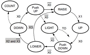
In the state transition diagram below, an additional state called ”LIGHT” has been added. Whenever the garage owner presses and releases the door control switch, the RAISE or LOWER state is active and the LIGHT state is simultaneously active.
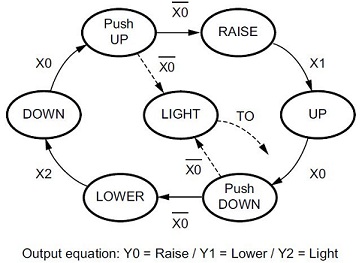
The line to the LIGHT state is dashed, because it is not the primary path. the LIGHT state can be thought of as a parallel process to the RAISE and LOWER states.
Notice the paths to the LIGHT state are not transition Jump to Stage (JMP) instructions, but Enable Stage (SGSET) instructions.
The path out of the LIGHT stage goes nowhere, indicating the LIGHT stage simply becomes inactive when the safety light goes off.
The modified stage program is shown below. The shaded areas indicate the program additions.
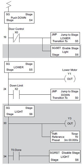
Notice the two new stage instructions introduced in these additions: the Enable Stage (SGSET) and Disable Stage (SGRST). The Enable Stage (SGSET) only enables the target stage and the Disable Stage (SGRST) only disables the target stage, they do not change the state of the stage in which the instructions are executed.
In the Push-UP stage S1, an Enable Stage (SGSET) instruction was added. When contact X0 opens, we transition from Push-UP stage S1 to two new stages: RAISE stage S2 and LIGHT stage S6. In the Push-DOWN state S4, we make the same addition of an Enable Stage (SGSET) instruction. Any time the door control push button is pressed the safety light turns on for the duration of the timer.
A three minute Timer is placed in the LIGHT stage S6. When the Timer expires it will reset the LIGHT stage with a Disable Stage command (SGRST).
Note: New stage programmers might be concerned about where to place the LIGHT Stage in the program and how to number it. Placement of the new stage in the program is not critical except that it cannot be the first stage in the program. Stages are not required to be sequentially numbered, simply choose an unused stage number and use it.
Note: Another concern that new Stage programmers might have is thinking that a stage has to be directly under the stage that transitions to it. While it is good practice to have the stage program mimic the sequential flow of the process because it makes following the stage flow easier to follow, there are no requirements that dictate the placement of stages within a program. The stage numbers and the instructions that reference them will determine the transition paths, not their stage number or location within the program.
So, in the LIGHT stage S6, the safety light is turned on by energizing Y3. The Timer also has power flow whenever the LIGHT stage is enabled. Three minutes later, when the Timer is done, a Disable Stage (SGRST) instruction is used to disable the LIGHT stage, essentially turning itself off and in doing so, the safety light will also be turned off.
While the LIGHT stage is active and the safety light is on, the stage transitions in the primary path continue to function normally and independently of the LIGHT stage. That is, the door can go up or down as many times as needed, but the safety light will be on for precisely 3 minutes from the first time the door control push button was pressed.
Add Emergency Stop Feature
The second feature added to the application is the ability to detect an obstruction and respond accordingly. Once more, start with a written description of the application, then make changes to the block diagram and the state transition diagrams as required, and only then make the necessary additions and/or changes to the stage program.
Most garage door openers will detect an object under the door when it’s being closed and halt further lowering of the door.
Usually implemented with a photocell (”electric-eye”), a door in the process of being lowered will halt and reverse direction when an obstruction is detected.
A new input (X3) from the photocell is added to the block diagram as shown to the right, which will be on if an object is in the path of the door.
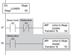
Additional logic is added at the top of the LOWER state to implement the new transition path.
Notice that if the door is being lowered and an obstruction is detected (input X3), the control process jumps to the RAISE state.
An interesting consideration is the potential that the down limit (X2) and the obstruction input (X3) could energize at the same moment. If that were to happen, the control process would transition to the Push-UP and DOWN states simultaneously, which is not the desired result.
Instead, the DOWN state can give priority to the obstruction by changing the transition condition to [X2 AND NOT X3].
The modifications needed to the LOWER stage (S5) logic are shown in the illustration below. The shaded ares indicate the changes and/or additions. This inter-lock logic will ensure that only one of the Jump to Stage (JMP) instructions will execute.
Add a Door Open & Close Counter
So the last feature to be added is the ability monitor the ”productivity” of the garage door opener process by counting the number of open/close cycles which occur. While there are several events that could be used to signal the garage door has completed an open/close cycle, this example will use the enabling of the DOWN stage as the event to signal that a cycle has occurred.
The state transition diagram now includes a new state called COUNT, which is enabled on the first scan of the program. Also note there is no transition out of the COUNT state; once it is enabled it will run until the program has ended.
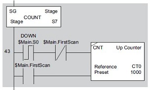
The DOWN stage has been changed to include a new rung that has an Enable Stage (SGSET) of the new COUNT stage S7. This example makes use of the $Main.FirstScan bit to enable the COUNT stage S7 on the first scan of the program.
A new COUNT stage S7 has been added to the example stage program. This stage contains an UP Counter instruction which will record the number of open & close cycles by using the stage bit ($Main.S0) of the DOWN stage S0 as the counter input.
Recall that the stage bits reflect whether the corresponding stage is enabled or disabled. Also recall they are referenced in the form <program name>.<stage number>. Assuming the garage door controller starts in the DOWN stage, a completed cycle would be a successful transition through the door opening stages and then returning to the DOWN stage.
So the event that will be used to trigger a cycle will be the enabling of the DOWN stage. The stage bit $Main.S0 comes on each time the DOWN stage S0 is enabled, so that bit will be used as the input to the counter.
To get an accurate count of the door’s open and close cycles, there is one exception condition that must be accounted for. Because the DOWN stage is the Initial Stage, it will be automatically enabled on the first scan, which will cause a false count, so an interlocking relay $Main.FirstScan has been added to the count input leg to prevent this.
The $Main.FirstScan is also used on the Counter’s Reset input to clear the count each time the program is run.
Stage Programming Concepts
Example 1 - A Simple 2-State Process
Example 2 - A Lamp On / Off Controller
Example 3 - A Garage Door Opener
Review - Steps to Writing Successful Stage Programs
Stage Programming Instructions
SGRSTR - Disable Range of Stages
SGDIVRG - Jump to Multiple Stages
SGCONVRG - Converge Multiple Stages to SG