Topic: DMD0501

SG - Stage
The Stage (SG) instruction marks the beginning of a stage in a Program. When a stage is enabled, all of the ladder logic within that stage is included as part of the current PLC scan; and when a stage is disabled, none of the ladder logic with that stage is included.
Each Program code block can have up to 128 stages which are numbered S0 through S127. Stages within a Program do not have to be numbered sequentially; stage numbers can be skipped. The stage number is simply an identifier, it does NOT imply sequence or order. There cannot be duplicate stage numbers in the same Program.
A Stage is enabled by a Jump To Stage (JMP), a Jump to Multiple Stages (SGDIVRG), an Indexed Jump (JMPI), or an Enable Stage (SGSET) instruction.
Each time a stage is enabled all rising-edge triggered contacts will energize and edge-triggered inputs on instructions will be ON during the first scan of a Stage if they are ON when the Stage is first enabled. The one notable exception rule are the counter instructions (Up Counter, Down Counter, Up / Down Counter, Global Up / Down Counter) which will not count if the count input is ON when the stage is enabled. These instructions require an OFF to ON transition AFTER the Stage is enabled before they will count.
Initial Stage
The Stage instruction that is physically the first stage in each Program - regardless of the stage number - is called the Initial Stage. It will be automatically enabled each time the Program is run. The Initial Stage has a double box border which will visibly distinguish it from the other stages in the Program. Other than being automatically enabled each time a Program is run, the Initial Stage operates just like a regular stage.
This instruction is a 'power-rail' instruction, meaning that it is displayed in the left-most column of the ladder diagram (the power rail). Creating new instances of this instructions is a bit counter-intuitive because they cannot be entered directly on the power rail in the Ladder Editor. The first step is to position the edit cursor in the output column (the far right) of the rung in the ladder logic diagram instead of positioning it against the power rail (the far left). At that point you can enter the instruction's mnemonic or double click on the instruction's name in the Instruction Toolbox. You can also drag / drop the instruction from the Toolbox anywhere on the rung and it will be created in the power rail of that rung.
Like all of the other stage programming instructions this one must be placed in a Program; stage instructions cannot be placed in a Task, a Subroutine, or an Interrupt Service Routine. Stage programming instructions can only reference stages in the same Program code block, they cannot reference stages in a different Program code block.
To switch between displaying the fully qualified stage reference ($Main.S0) and the abbreviated name (S0), go to the View -> Options -> Ladder Tab -> Misc. Options and check the 'Abbreviate Stage Names (Use S0 over $Main.S0)' option.
For a complete discussion on Stage Programming and how to use the Stage programming instructions effectively, refer to the Help Topic on Stage Programming Concepts.
Parameters:
Note: Use the F9 key or click the 'three dot box' at the right edge of the parameter field to open the Default Element Selection Tool (the Element Picker or the Element Browser) or use the Down-Arrow key (Auto-Complete) on any parameter field to see a complete list of the memory locations that are valid for that parameter of the instruction.
Stage is the reference number of the Stage to create. The stage reference can be entered using its fully qualified name (for example MyProgram.S0 through MyProgram.S127) or simply its stage number (for example S0 through S127).
Termination Scan Behavior:
When a Stage is disabled by a Jump
To Stage (JMP), a Jump to Multiple Stages (SGDIVRG), an Indexed Jump (JMPI),
a Disable Stage (SGRST), or a Disable Range of Stages (SGRSTR)
instruction, the following actions will occur on its termination scan:
All output coils (OUT) within that stage will be turned off.
All Timers within that stage will be reset.
Edge triggered contacts within that stage will be turned off.
Edge triggered instructions within that stage will be reset.
Refer to the Termination Behavior Help topic for more information about the termination scan and a for list of all the programming elements that have termination logic.
Status Display:
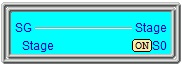
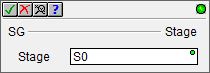
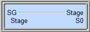
The status display of the stage instruction will indicate the ON / OFF condition of the Stage bit, and if ON, the entire box will be highlighted.
See also:
SG - Stage
SGRSTI - Indexed Disable Stage
SGRSTR - Disable Range of Stages
SGDIVRG - Jump to Multiple Stages
SGCONVRG - Converge Multiple Stages to SG
Related Topics:
Stage Programming Concepts
Example 1 - A Simple 2-State Process
Example 2 - A Lamp On / Off Controller
Example 3 - A Garage Door Opener
Review - Steps to Writing Successful Stage Programs
Example:
Description of a Typical Stage Diagram:
This is a stage diagram of a simple sequence control that would fill a vessel, stir its contents and then drain. It is good to imagine the sequence before actually writing the ladder logic.
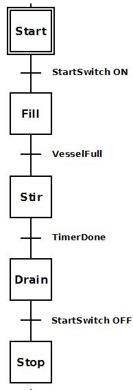
Initially stage 'Start'
Stage 'Fill' fills the vessel. Once the vessel is full (VesselFull = ON), the process transitions to stage 'Stir'.
Stage 'Stir' stirs for a period of time. Once the time to stir is complete (TimerDone = ON), the process transitions to stage 'Drain'.
Stage 'Drain' empties the contents of the vessel. Once it is decided the vessel is drained, the StartSwitch is flipped OFF and the job is done.
Ladder Logic for the above Stage Diagram:
This is a ladder logic equivalent to the above stage diagram.
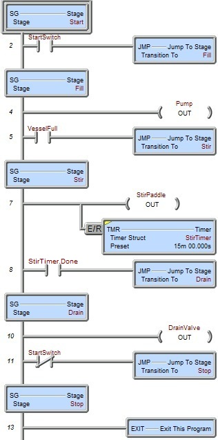
Once the Program code block containing this stage is first enabled to run, the initial stage 'Start' will be enabled because it is the initial stage (designated by the double border). None of the ladder logic in other stages ('Fill', 'Stir', 'Drain', 'Stop') is executed; only Rung 2. Once StartSwitch comes ON the JMP (Jump To Stage) instruction is executed. This instruction disables stage 'Start', and enables stage 'Fill' so that only the ladder logic in stage 'Fill' is being executed (i.e. Rungs 4-5).
Once stage 'Fill' is enabled Pump turns ON to power the pump motor so that product will begin to fill the vessel. Once the level detector input, VesselFull comes ON, the JMP instruction is executed. This instruction disables stage 'Fill' and enables stage 'Stir'. Also, since stage 'Fill' is now disabled, all of the OUT coils in that stage will be turned OFF (i.e. Pump will go OFF).
Once stage 'Stir' is enabled StirPaddle turns ON to power the stir-paddle motor so that the product can be stirred. Also TMR (StirTimer) begins to time. After 15 minutes of stir time, TimerDone bit comes ON which will execute the JMP instruction. This instruction disables stage 'Stir' and enables stage 'Drain'. Also, since stage 'Stir' is now disabled, all the OUT coils in that stage will be turned OFF and all the timers will be reset.
Once stage 'Drain' is enabled DrainValve turns ON to open the valve for the product to drain out of the vessel. Once StartSwitch turns OFF the JMP instruction is executed. This instruction disables stage 'Drain' and enables stage 'Stop'. Since stage 'Drain' is now disabled, all OUT coils in that stage will be turned OFF.
Once stage 'Stop' is enabled the EXIT instruction is executed and the Program code block containing this stage is exited.
If this sequence need be repeated, then the Program code block containing this stage would have to be run again.
It is possible, however, that instead of exiting the Program code block, the JMP instruction in stage 'Stop' could merely jump back to stage 'Start' using a JMP instruction instead of an EXIT. In this manner the stage would repeat indefinitely as long as the Program code block is not halted.