Topic: DMD0272

Cross Reference View
The Cross Reference View provides a table of element and instruction
usage information. The Cross Reference View can be opened by selecting
the Tools -> Cross Reference...
menu selection, or by clicking the Xref
button on the Tools bar, or by the Ctrl+Y
keyboard combination. The Cross Reference View operates in one of the following modes (each
of which is discussed in more detail below):
-
Cross Reference mode which operates like a database query in that the toolbar buttons define a 'query' that generates a list of elements and instructions that meet the requirements of that query.
-
Element Usage mode displays ranges of elements and indicates which elements within those ranges are currently being used in the project.
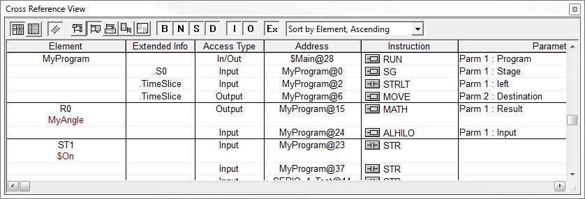
As much of the following information as is appropriate is displayed for each element in the cross reference list:
Xref Element is the element id or nickname that has been referenced in the program.
Note: double-click on the Element to invoke the Element Browser.
Xref Extended info will show any casting and structure member information.
Xref Access Type is the Input, Output, or Input / Output access type for that specific parameter.
Xref Address is the fully qualified memory address in the PLC displayed as <code-block>@<address>.
Xref Instruction is the name of the instruction that contains the element.
Xref Parameter shows additional information which includes the element’s Parameter Info (where appropriate).
Note: Double-clicking on the entries of the Extended Info, Access Type, Address, Instruction, or Parameter fields moves the Ladder View's edit cursor to the location in the program where the element is used.
Cross Reference Mode
When in Cross Reference Mode the toolbar buttons define the scope of the query and the element type constraints that will be used. The toolbar buttons are 'sticky' meaning that, to enable that button's function, left-click it once and the button will remain in the 'pressed state, left-click again to disable that button's function.

The Cross Reference Mode toolbar buttons are (from left to right) :
The first group of three buttons determine the Mode of the Cross Reference View.
Cross Reference Mode enable sets the current mode to Cross Reference Mode.
Element Usage Mode enable sets the current mode to Element Usage mode (see description below)
Follow Ladder Cursor: if enabled, only the topmost element in the cross reference table will follow the Ladder Edit cursor as it is moved around the Ladder View. If disabled, the cross reference table can be navigated with its cursor keys and the scroll bars.
The next group of four buttons determine
how much of the project's ladder logic will be looked at to generate the
set of cross referenced points which will then be displayed in the cross
reference table.
XRef Point Scope limits the set of cross referenced points to the active Ladder View’s edit cursor.
XRef Instruction Scope (the default) limits the set of cross referenced points to the instruction where the active Ladder View’s edit cursor is currently positioned.
XRef Rung Scope limits the set of cross referenced points to all of the instructions on the rung where the active Ladder View’s edit cursor is currently positioned.
XRef Block Scope limits the set of cross referenced points to all of the rungs of the single code-block in the active Ladder View.
XRef Full Scope the cross reference query looks at all of the code-blocks in the project.
The next set of 4 buttons ( B N S D ) are used to specify the set of cross referenced points by filtering elements out of the list based on the element’s data-type. Clicking one of the buttons will enable the inclusion of that data type in the set of cross referenced points; if a button is NOT clicked, elements with that data type will NOT be included in the list.
XRef Include BITs will include elements that are BIT data types in the cross reference table.
XRef Include NUMERICs will include elements that are NUMERIC data types in the cross reference table.
XRef Include STRUCTs will include elements that are STRUCTURES in the cross reference table.
XRef Include DEVICEs will include elements that are DEVICES in the cross reference table.
The next set of 2 buttons ( I O ) are used to further refine the set of cross referenced points by filtering elements out of the list based on the element’s access type. Clicking one of the buttons will enable the inclusion of elements that are used in instructions as that access type in the set of cross referenced points.
XRef Include INPUTs will include ONLY points used as INPUTS to instructions in the cross reference table.
XRef Include OUTPUTs - include ONLY points used as OUTPUTS to instructions in the cross reference table
The next button ( Ex ) is used to optionally expand simple ranges so that the cross reference will additionally include an entry for each element that is referenced in ranged instruction SETR - Set Range, MOVER - Move Range, etc.). For example, a SETR instruction that references C100 through C120, would have a single entry in the Cross Reference named "C100 thru C120".
Ex is disabled : only the single range entry (C100 - C120) will appear in the Cross Reference list.
Ex is enabled (the default) : the single range entry (C100 thru C120 ) and individual entries for C100, C101, C102 through C120 will appear in the Cross Reference list.
The final selection on the toolbar is the sort order drop-down list which specifies how the list of elements will be organized. Select one of the following options:
Sort By Element, Ascending : the list is organized alphabetically by the contents of the Element field .
Sort By Element, Descending : the list is organized alphabetically in reverse order by the contents of the Element field.
Sort By Nickname, Ascending : the list is organized alphabetically by the Nicknames.
Sort By Nickname, Descending : the list is organized alphabetically in reverse order by Nicknames.
Sort By Data-Block/Number ID : the list is organized alphabetically by the Data-Block type and ID in the order they appear in the Memory Configuration.
Element Usage Mode
The Element Usage Mode provides an efficient view of the memory elements that are being referenced, which are free, and whether or not they are being used in a ranged instruction. The elements are shown in groups of 8, 10, or 16 bits as determined by the current Usage Field Size setting.
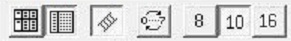
The Element Usage Mode toolbar buttons are (from left to right) :
The first group of three buttons determine the Mode of the Cross Reference View.
Cross Reference Mode enable sets the current mode o Cross Reference Mode (see description above).
Element Usage Mode enable sets the current mode to Element Usage mode.
Follow Ladder Cursor : if enabled, only the topmost element in the cross reference table will follow the Ladder Edit cursor as it is moved around the Ladder View. If disabled, the cross reference table can be navigated with its cursor keys and the scroll bars.
Reverse Usage toggles the display order of the elements in the range, from MSB is the left-most element -to- MSB is the right-most element.
The final set of 3 buttons are used to define the number of elements to display in each range
8 / 10 / 16 sets the usage field display to 8 10, or 16 elements respectively.
Element is the range of elements.
Range Displays : the following icons can be shown in a cell for a given element:
X means the point is used explicitly in the project.
[ means the point is used at the beginning of a range of contiguous points.
– means the point is implicitly used within a range, but is not referenced explicitly in the project.
] means the point is used at the end of a range of contiguous points.
I means - the point is used both as the beginning of a range and at the end of a range.
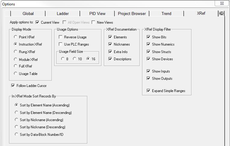
Cross Reference Options:
The selections described above affect only the current cross reference view. To make the selection permanent use the XRef Options dialog, which can be opened by clicking the View-> Options menu selection and then selecting the XRef tab, or by right-clicking anywhere within the Cross Reference view itself and selecting Options. The same selections that are listed above will be available on the Options dialog.
See Also: