Topic: DMD0341

GSREGRD - GS EDrive Register Read
The GS EDrive Register Read (GSREGRD) instruction is used to perform a series of read operations from parameter values in GS Series AC Drives which is connected to a GS-EDRV100. The instruction can contain up to 50 individual READ operations which are performed in the order that they are listed in the instruction. If all of the listed READ operations were completed successfully the On Success selection will be executed. Processing of the listed READ operations will stop after the first failure and the On Error condition will be executed.
This instruction can only be performed by the Ethernet I/O Master through a GS-EDRV100 which is connected to the GS Drive's serial port. When the Ethernet I/O Master is connect to a GS-EDRV100 slave it automatically reads a fixed set of parameters from the drive and places the data in the member fields of a GS Drive structure. This instruction is intended to read values to parameter locations that are NOT already being read by that process.
Parameters:
Note: Use the F9 key or click the 'three dot box' at the right edge of the parameter field to open the Default Element Selection Tool (the Element Picker or the Element Browser) or use the Down-Arrow key (Auto-Complete) on any parameter field to see a complete list of the memory locations that are valid for that parameter of the instruction.
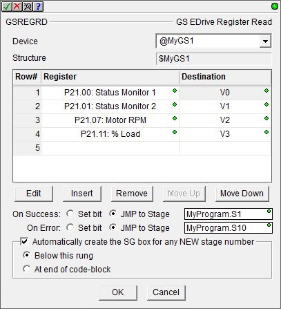
Device selects which of the configured GS EDrive devices to use. Structure is the name of the system-created structure for the selected GS EDrive.
create module indicates that there are no GS EDrive Devices configured to perform this instruction, selecting this option will open the Module Configuration section of the System Configuration utility where a GS EDrive Device can be created.
The center section displays the table of individual write operations that will be performed each time this instruction is executed. The buttons below the table are used to manage the rows in the table: Edit opens the row editor to change the currently selected row. Insert inserts an empty row before the currently selected row and opens the row editor. Remove removes the currently selected row. Move Up / Move Down moves the currently selected row up one row or down one row in the table respectively.
The row editor is used to add a new entry to the table, or modify an existing entry in the table. To open the row editor, double-click on the row, or highlight a row then click the Edit or Insert button.
Source
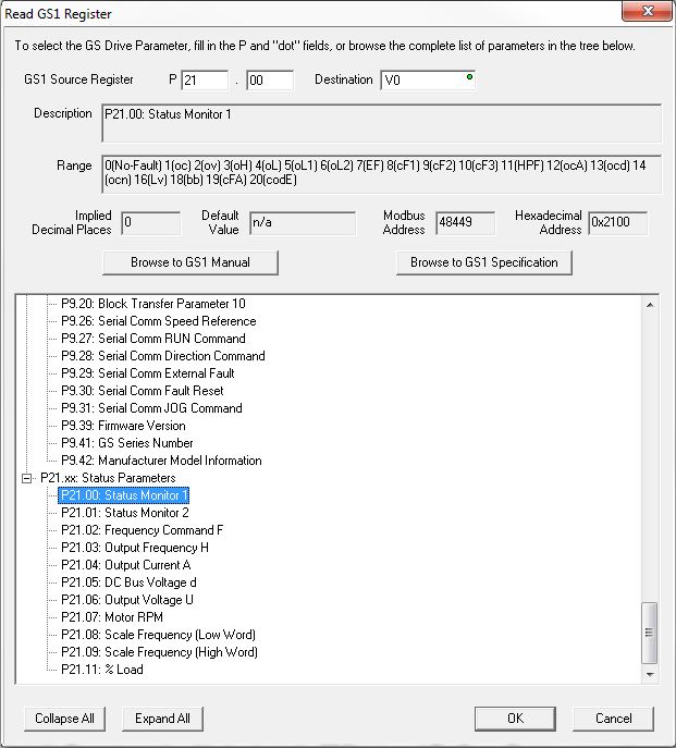
Register is the Parameter number of the location in the
GS Drive to read. The Source Register entry can be made by entering the
P XX.yy values in the two location in the upper section, or by selecting
one of the entries from the tree-control in the lower section. The Description,
Range, Implied Decimal Places, Default Value, Modbus Address, and Hexadecimal Addresss fields will display
the appropriate information as the Source Register data is changed.
Destination specifies the memory location in the PLC to store the value read from the GS Drive.
The Browse to GSx Manual and Browse to GSx Specification buttons will open the default web browser, which will then open a page on Automationdirect's web site that contains links to the User Manual or the Specification page for the type of GS Drive configured. These two options require a functional connection to the Internet and a PDF viewer.
The Collapse All button will collapse the Parameter Range lists so that only the Parameter Ranges are shown. The Expand All button will fully expand all of the Parameter Ranges lists so that each selection in each Range is shown.
The On Success and On Error parameters specify what action to perform when this instruction completes. You do not have to use the same type of selection for both On Success and On Error.
If the Set Bit selection is used for either On Success or On Error, the specified BIT location will be SET OFF when the instruction is first enabled and will remain OFF until the instruction completes. Once complete, the appropriate Success or Error bit location ON. The specified Bit location is enabled with a SET (Latch) operation meaning that it will remain ON even if the input logic for the instruction goes OFF.
If the JMP to Stage selection is used for either On Success or On Error the target Stage must be in the same Program code-block as this instruction, you cannot specify a target Stage that exists in a different Program code-block. When the operation finishes, the target Stage will be enabled the same way as a standalone Jump to Stage (JMP) instruction would do it. The JMP to Stage option will only be available if this instruction is placed in a Program code-block.
On Success selects which of the following actions to perform if the operation is successful:
- Enable SET Bit then specify any writable bit location.
- Enable JMP to Stage then specify any
Stage number from S0 to S127 in the current Program code-block.
On Error selects which of
the following actions to perform if the operation is unsuccessful:
- Enable SET Bit then specify writable bit location.
- Enable JMP to Stage then specify any Stage number from S0 to S127 in the current Program code-block.
If either the On Success or On Error selections are set to JMP to Stage, Automatically create the SG box for any NEW stage number will be enabled which will automatically create any target stage that does not already exist.
- Below this rung will create the new target stage on a new rung following this instruction.
- At end of code-block will create the new target stage as the last rung of this Program.
Status Display
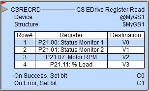
The red triangle in the upper left corner of the status display indicates this is a Fully Asynchronous instruction.
The gray triangle at the right end of the input leg indicates the input is edge-triggered, meaning this instruction will execute each time the input logic transitions from OFF to ON.
See Also:
GSREGRD - GS EDrive Register Read
GSREGWR - GS EDrive Register Write
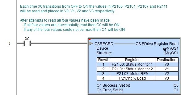
Rung Example: