Topic: DMD0067

DRUM - Drum
The Drum (DRUM) instruction is used to mimic the operation of a mechanical Drum (sometimes called a drum sequencer). Drum instructions are well suited for repetitive processes that consist of a finite number of steps. As such, they can do the work of many rungs of ladder logic with elegant simplicity.
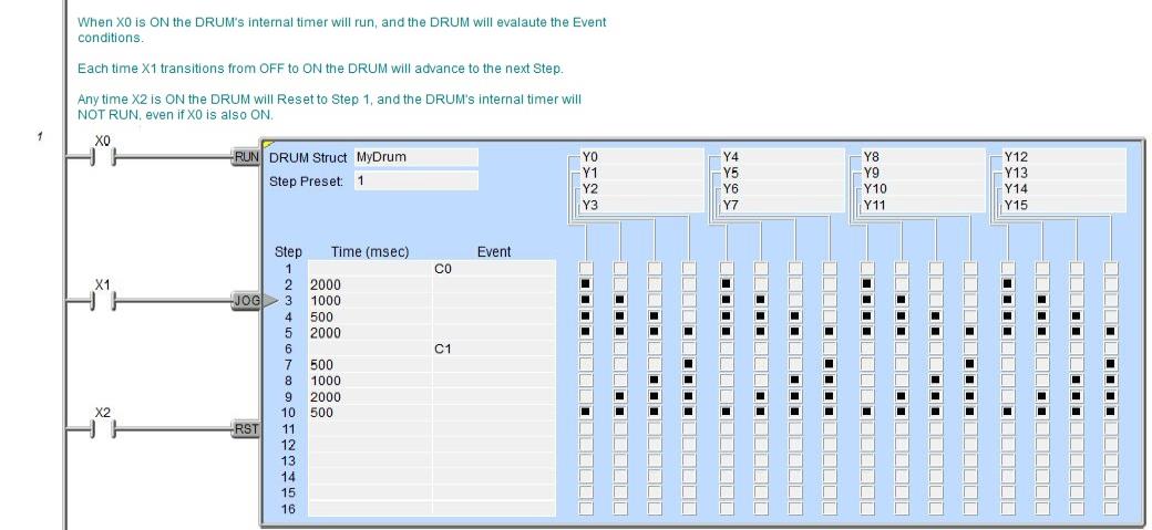
Important Note: the outputs specified in the Drum instruction are enabled and controlled by the DRUM any time the CPU is in Run Mode - the Drum's RUN input does not have to be ON, and the Reset input does not disable the outputs. When the CPU enters Run Mode, the Drum instruction's outputs automatically turn ON or OFF according to the pattern of the preset step. This includes any effect of the optional Output Mask.
Drum instruction parameters are best described by examining the mechanical drum after which the Drum instruction is modeled. The mechanical drum is typically a cylinder with pegs on its curved surface. The pegs are populated in a particular pattern which represents a set of desired actions for machine control. A motor or solenoid rotates the drum a precise amount at specific times. During this rotation, stationary wipers sense the presence of pegs (present = ON, absent = OFF). This design makes or breaks electrical contact with the wipers, creating electrical outputs from the drum. The outputs are wired to devices on a machine for On / Off control. The contact closure of each wiper generates a unique on / off pattern called a sequence. Because the drum is circular, it automatically repeats the sequence once per rotation.
Drums have a finite number of positions within one rotation; these are called Steps.
At power-up or any time the Drum's RST input (3rd input leg) is ON the Drum is reset to a predetermined step called the Step Preset.
The Drum rotates from one step to the next based on its internal timer, or some Event, or a combination of the internal timer and the Event.
If needed, a machine operator can manually increment the drum step using a Jog control (2nd input leg) on the drum's drive mechanism.
In Do-more Designer the mechanical drum is represented in chart form. Imagine slicing the surface of a hollow drum cylinder between two rows of pegs, then pressing it flat. The drum can now be viewed as a chart. Each row of the chart represents a Step, numbered 1 through 16. Each column represents an output, numbered 0 through 15 (to match word bit numbering). The grid of empty squares on the right represents the surface of the drum where the pegs would be placed. Clicking on a square fills in that square, and this represents the ON state. On the mechanical drum this would be a peg, and the open squares would represent empty peg sites.
Drum Inputs
The first input leg (RUN) is the Run input. When this input logic is ON the Drum's internal timer is running. When this input logic is OFF the Drum's internal timer will stop. When the Run input goes OFF the internal Timer will stop at the current value and will resume at that time value when the Run input goes back ON .
The second input leg (JOG)
is the Jog input. The Jog input is Edge Triggered![]() Each time the input logic transitions from OFF to ON this instruction will execute. With each execution, this instruction will run to completion even if the input logic transitions to OFF before the instruction completes.,
meaning that each time the Jog input logic transitions from OFF to ON
the Drum is advanced to the Next Step regardless of the state of the Time
or Event fields.
Each time the input logic transitions from OFF to ON this instruction will execute. With each execution, this instruction will run to completion even if the input logic transitions to OFF before the instruction completes.,
meaning that each time the Jog input logic transitions from OFF to ON
the Drum is advanced to the Next Step regardless of the state of the Time
or Event fields.
The third input leg (RST) is the Reset input. When this input logic is ON the Drum will move to the Preset step and the Drum's internal timer will reset to 0 and will remain in the Reset state as long as this input remains ON. The Reset input has priority over the Run and Jog inputs, meaning that if either the Run or Jog inputs are ON at the same time as the Reset input, the Drum will NOT Run and the Jog input will NOT cause the Drum to change the current Step.
Parameters:
Note: Use the F9 key or click the 'three dot box' at the right edge of the parameter field to open the Default Element Selection Tool (the Element Picker or the Element Browser) or use the Down-Arrow key (Auto-Complete) on any parameter field to see a complete list of the memory locations that are valid for that parameter of the instruction.
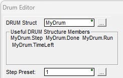
DRUM Struct specifies the associated structure this Drum instruction will use. This can be a either a
new Heap Item![]() A Heap item and it's associated memory are not preallocated in a default Memory configuration. They are single items as opposed to one entry of a memory block. A Heap Item can be created in the Memory Configuration or be created when the instruction using it is added to the ladder diagram. that will be created, or a structure from an existing block of Drum
structures.
A Heap item and it's associated memory are not preallocated in a default Memory configuration. They are single items as opposed to one entry of a memory block. A Heap Item can be created in the Memory Configuration or be created when the instruction using it is added to the ladder diagram. that will be created, or a structure from an existing block of Drum
structures.
Useful DRUM Structure Members shows some of the structure members that will be created using the DRUM Struct name. The structure fields are the ones that will typically be used in the ladder logic program to control the DRUM's execution and monitor its runtime status. There is a complete list of the structure members at the end of this help topic.
Step Preset specifies which Step in the Drum to start executing when the Drum is first enabled, and whenever the DRUM is Reset. This can be any value between 1 and 16 or any readable numeric location. If an invalid Step number is entered the Status Bit $OutOfRange (ST132) will be ON and an error message will be generated.
The Step Preset is typically the constant value 1. One situation where use of a variable location makes good sense is when the Drum has some initializing steps that need to run only once, meaning the Drum initially needs to start at Step 1, but on subsequent passes it needs to start at a later Step, skipping over the initializing steps.
Note: If you choose to create a new heap item, be aware that this will change the System Configuration, and changes to the System Configuration can only be saved to the controller in PROGRAM mode. Run mode updates can not be performed until these System Configuration changes have been saved to the PLC. For more information on heap items and preallocating one or more Drums refer to the Memory Configuration section in the System Configuration utility.
If the DRUM Struct field is changed for any reason, this dialog will be displayed.:
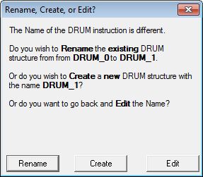
Choosing Rename will rename the existing DRUM structure. This will cause a change to the System Configuration which can only be saved to the CPU
in PROGRAM mode. One situation where this would likely occur is after a copy / paste operation of an existing DRUM instruction; the Drum structure used in the
newly pasted DRUM instruction must be changed.
Choosing Create will create a new heap item, and the existing DRUM structure will not be affected. This will cause a change to the System
Configuration which can only be saved to the controller in Program mode. One situation where this would likely occur is after a copy / paste operation
of an existing DRUM instruction; the Drum structure used in the newly pasted DRUM instruction must be changed.
Choosing Edit will return to the Drum Editor where the name can be changed.
Adding Steps to a Drum
Each Step in a Drum is represented as a row that consists of a dwell Time for that step, and / or a terminating Event for that step, and an ON / OFF designation for each of the discrete Outputs in the Drum.
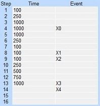
A Step does NOT require both a Time and an Event, a step can have either a Time or an Event or both.
Time Only : specify the amount of time (in milliseconds) to dwell on the current step. This can be any positive integer between 0 and 2147483647 or any readable numeric location. When the drum enters a Step, it sets the output pattern indicated then it begins timing down from the specified Time value. When the Time has expired the Drum moves to the next Step.
Event Only : when the Drum enters a Step, it sets the output pattern indicated then begins polling the Bit location programmed as the Event for that step. As soon as the Event is ON the Drum transitions to the next Step.
Timed Event : the time field specifies the amount of time (in milliseconds) to dwell when the element specified in the Event field is ON. The Step will not time when the Event field element is OFF. This can be any positive integer between 0 and 2147483647 or any readable numeric location. When the Drum enters a Step, it sets the output pattern indicated then it begins timing down from the specified Time value. When the Time has expired the Drum moves to the next Step.
Drum instructions do NOT require that all of the Steps be utilized. A Step that has neither a Time or an Event will be skipped. Once the Drum has executed the last Step, the outputs remain in the pattern defined for the last Step.
The Output Control Grid uses rows and columns of squares to mimic the pegs and gaps of the mechanical drum.
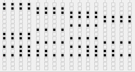
A square that is empty represents a gap (or missing peg, or OFF state). Clicking on the square with the mouse (or the space bar on the keyboard) will fill in the square, which represents a peg (or ON state). Clicking and dragging the mouse cursor over a group of squares will select multiple rows and columns and will fill in all of the selected squares. Clicking on a square that has already been filled in will empty that square.
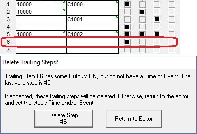
A Step that has been configured to have one or more Outputs ON is considered valid only if that Step also has either a Time or Event configured. If there is a Step BEFORE the last valid Step that has Outputs ON but no Time or Event, a Warning message is displayed and you will be prompted to add a Time or Event for that Step.
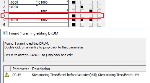
If there is a Step AFTER the last valid Step which has Outputs ON but no Time or Event, you will be prompted to add a Time or Event, or that Step will be deleted from the Drum when it is saved.
The 5 buttons at the bottom of the editor are used to manage whole steps within the DRUM's table of steps.

Clicking Insert Step will add a new empty step at the current step after shifting any existing steps down one position in the table. If there is no space in the table to insert the empty step, you will be asked to confirm the loss of the last step in the table.
Clicking Duplicate Step will add a copy of the current step after shifting any existing steps down by one position in the table. If there is no space in the table to add the duplicate step, you will be asked to confirm the loss of the last step in the table.
Clicking Remove Step will delete the current step from the table, then shift any steps below the current step up by one position in the table.
Clicking Move Step Up will move the current step one position toward the top of the table.
Clicking Move Step Down will move the current step one position toward the bottom of the table.
Selecting Drum Outputs
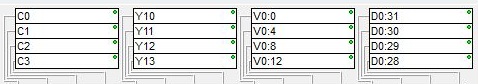
The Output section contains 4 groups of 4 entries, for a total of 16 possible outputs. Entries in these Output locations can be any writable Bit memory location, including individual Bit locations (C0, Y0, etc.) and offset values in numeric locations (V0:0, D0:31, etc.). Each Output is 'connected' to a column in the Output Control Grid and turned ON an OFF by the state for each Step as the Drum moves through each of the Steps defined in the Output Control Grid. Drum instructions do NOT require that all of the Output entries be used.
Using the Optional Output Masks
Drum instructions can have an optional Output Mask for each Step which will only allow the Discrete Output to change if the corresponding bit in the mask is set to 1. If this bit in the mask is 0, the state of the Output is not changed by the Drum. Output Masks are traditionally used to override the Drum's runtime control of its outputs, giving other parts of the program the ability to change the Drum's outputs if needed.
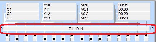
Output Mask : requires up to 16 consecutive DWord (32-bit) locations; one DWord for each of the possible 16 Steps. This field specifies the first DWord location of the range that will be used as Output Masks. The range of Output Mask addresses is displayed between the Output groups and the first step's Output grid pattern, in the above example, the Drum has 14 steps, and will use the 14 DWord D1 through D14 as Output Masks.
The Output Mask address for a specific step is offset from the first address in the range, based on its step number. For example, the Output Mask address for step 1 is the first address in the specified DWord range, the Output Mask for step 7 would be the seventh DWord address in the specified range, etc. Each Discrete Output in the Drum is labeled 0 through 15. These labels correspond to that specific bit in the step's Output Mask word.
Note: be aware of the bit ordering when entering values for the Output Mask, bit 0 (the mask bit for Output 0) is on the far left, and bit 15 (the mask bit for Output 15) is on the far right, which is backwards from the way traditional Hexadecimal or Decimal values are displayed. The Drum instruction only uses the lower 16 bits of each Output Mask address, upper 16 bits of each Output Mask are reserved for future use. Use bit casting to reference a specific bit in a Step's mask register, for example, D1:0 to reference the first Step's mask for Output 0, or D14:7 to reference the 14th Step's mask for Output 7.

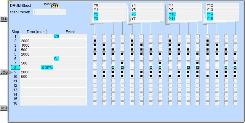
With status enabled, the current memory location being used as the mask is shown, and each bit in the Output Mask that is ON (has a value of 1) will be displayed as a "connector" between the Output Control Grid and the Outputs; and each bit that is OFF (has a value of 0 will be displayed as a gap.
Data View Display Formats
There are 4 variations of the Data View display of a drum structure, each with different amounts of data and / or different display orientations. These formats are for display purposes only, the structure's variables cannot be edited when displayed using any of these display formats.
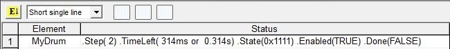
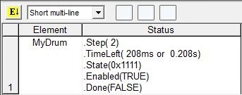
Short Multi-Line (default):

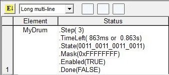
Long Multi-Line:
Drum Structure Members
All Drums have an associated structure with fields that can be used in the ladder program. The structure fields are updated each time the Drum instruction is processed during the PLC scan. The syntax for using them is <drum structure>.<field name>; for example MyDrum.TimeLeft.
.Jog (Read-only) is a Bit location that will be ON when the Jog input leg is ON, and OFF when the Jog input leg is OFF.
.Run (Read-only) is a Bit location that will be ON when the Run input leg is ON, and OFF when the Run input leg is OFF.
.Reset (Read-only) is a Bit location that will be ON when the Reset input leg is ON, and OFF when the Reset input leg is OFF.
.Done (Read-only) is a Bit location that will be ON when the Drum has completed the last step, and OFF when the Drum has not finished the last step.
.Step (Read-only) is an unsigned Byte that contains the step number in the Drum that is currently executing.
.Mask (Read-only) is a 32-bit unsigned value that contains the current Output Mask value : this value is best viewed in Hexadecimal or Binary format.
.State (Read-only) is a 32-bit value that contains the current Step's ON / OFF state of the 16 outputs BEFORE any mask state is applied. The DWord location will contain a 1 for each output that should be ON and a 0 for each output that should be OFF.
.TimeLeft (Read-only) contains the amount of execution time (in milliseconds) remaining for the currently executing Step in the Drum (in milliseconds).
See Also:
Related Topics:
TDOPRESET - Table Driven Output Preset Table (BRX only)
TDOPLS - Table Driven Output Programmable Limit Switch (BRX only)
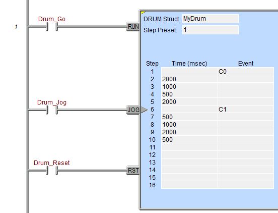
Rung Example: